SPEC NO: DSAD1513
REV NO: V.1
DATE: APR/06/2003
PAGE: 1 OF 4
APPROVED: J. Lu
CHECKED: Joe Lee
DRAWN: Z.Y.YANG
SURFACE MOUNT DISPLAY
Features
l
0.4INCH DIGIT HEIGHT.
l
LOW CURRENT OPERATION.
l
EXCELLENT CHARACTER APPEARANCE.
l
I.C. COMPATIBLE
l
MECHANICALLY RUGGED.
l
STANDARD : GRAY FACE, YELLOW
FLUORESCENT SEGMENT.
l
PACKAGE : 500PCS / REEL.
Notes:
1. All dimensions are in millimeters (inches), Tolerance is
Ý
0.25(0.01")unless otherwise noted.
2. Specifications are subject to change without notice.
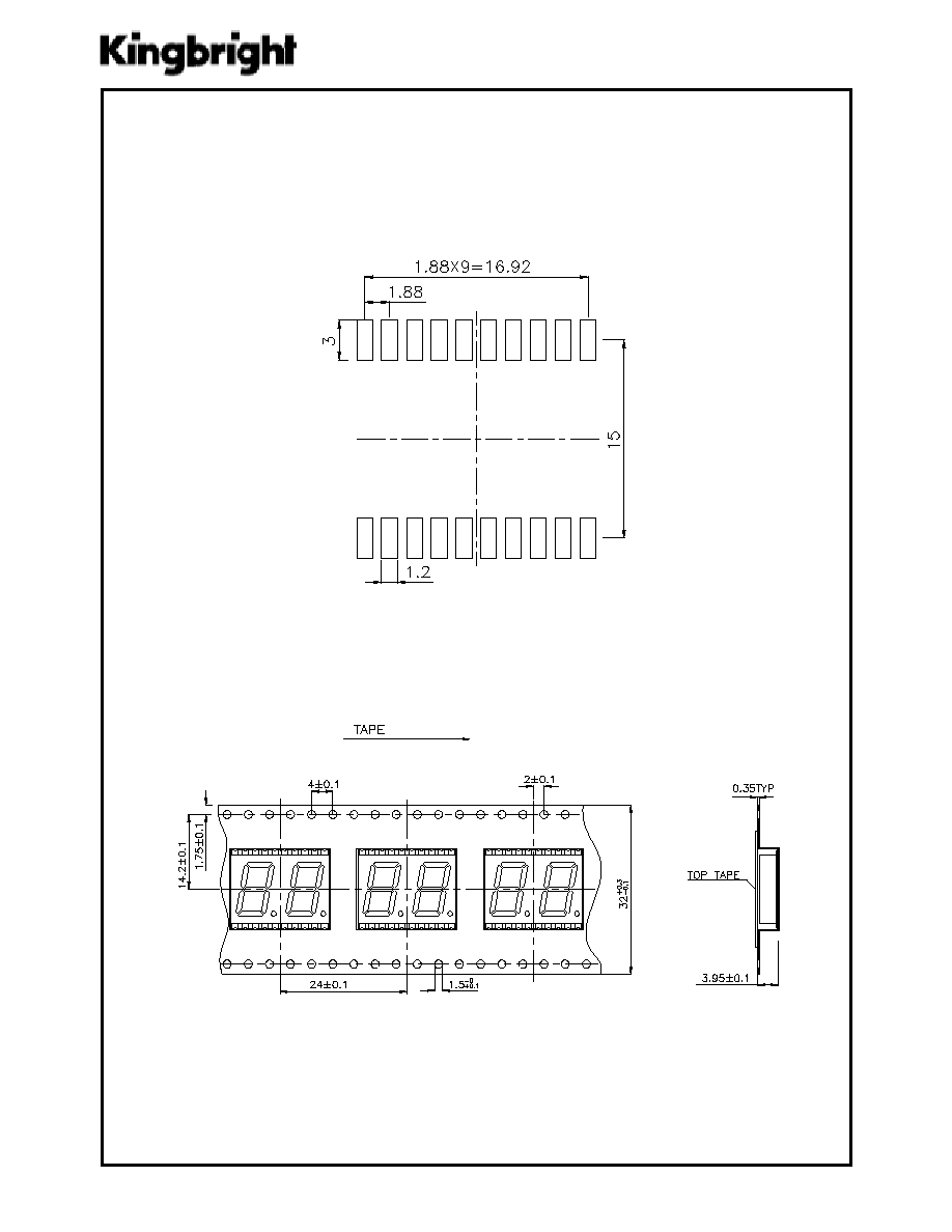
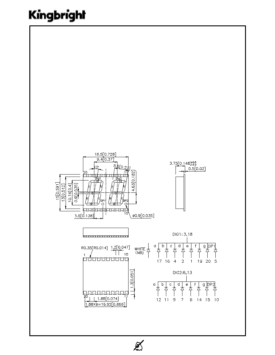
Package Dimensions & Internal Circuit Diagram
APDC04-41MWFA WHITE
Description
The source color devices are made with GaN on SiC
Light Emitting Diode.
Static electricity and surge damage the LEDS. It is
recommended to use a wrist band or anti-electrostatic
glove when handling the LEDs.
All devices, equipment and machinery must be
electrically grounded.
SPEC NO: DSAD1513
REV NO: V.1
DATE: APR/06/2003
PAGE: 2 OF 4
APPROVED: J. Lu
CHECKED: Joe Lee
DRAWN: Z.Y.YANG
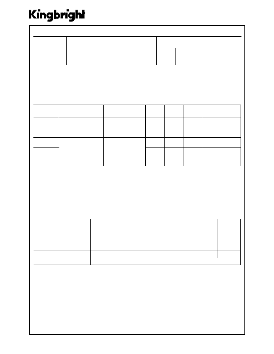
Selection Guide
Absolute Maximum Ratings at T
A
=25
¯¯
¯¯
¯
C
Electrical / Optical Characteristics at T
A
=25
¯¯
¯¯
¯
C
lo
b
m
yS lo
b
m
yS lo
b
m
yS lo
b
m
yS lo
b
m
yS
ret
e
m
ar
a
P
ret
e
m
ar
a
P
ret
e
m
ar
a
P
ret
e
m
ar
a
P
ret
e
m
ar
a
P
ec
iv
e
D ec
iv
e
D ec
iv
e
D ec
iv
e
D ec
iv
e
D
.p
yT .p
yT .p
yT .p
yT .p
yT
.x
a
M .x
a
M .x
a
M .x
a
M .x
a
M
sti
n
U sti
n
U sti
n
U sti
n
U sti
n
U
sn
oit
id
no
C
ts
eT
sn
oit
id
no
C
ts
eT
sn
oit
id
no
C
ts
eT
sn
oit
id
no
C
ts
eT
sn
oit
id
no
C
ts
eT
V
F
eg
atl
oV
dr
a
wr
oF
eti
h
W
8.
3
5.
4
V
I
F
A
m
02
=
I
R
tn
err
u
C
es
re
ve
R
eti
h
W
01
Au
V
R
V
5
=
X
se
ta
ni
dr
oo
C
yti
cit
a
m
or
h
C
eti
h
W
33
.0
Y
43
.0
C
ec
na
tic
ap
a
C
eti
h
W
00
1
Fp
V
F
zH
M
1=
f,
V
0=
ret
e
m
ar
a
P
ret
e
m
ar
a
P
ret
e
m
ar
a
P
ret
e
m
ar
a
P
ret
e
m
ar
a
P
eti
h
W eti
h
W eti
h
W eti
h
W eti
h
W
sti
n
U sti
n
U sti
n
U sti
n
U sti
n
U
no
ita
pi
ss
id
re
w
o
P
50
1
W
m
tn
err
u
C
dr
a
wr
oF
C
D
03
A
m
]1[
tn
err
u
C
dr
a
wr
oF
ka
e
P
05
1
A
m
eg
atl
oV
es
re
ve
R
5
V
er
ut
ar
ep
m
eT
eg
ar
ot
S/
gn
ita
re
p
O
04
-
¯
58
+
oT
C
¯
C
.o
N
tra
P
.o
N
tra
P
.o
N
tra
P
.o
N
tra
P
.o
N
tra
P
ec
iD ec
iD ec
iD ec
iD ec
iD
ep
yT
sn
eL
ep
yT
sn
eL
ep
yT
sn
eL
ep
yT
sn
eL
ep
yT
sn
eL
)d
cu
(v
I
)d
cu
(v
I
)d
cu
(v
I
)d
cu
(v
I
)d
cu
(v
I
A
m
02
@
no
itp
irc
se
D
no
itp
irc
se
D
no
itp
irc
se
D
no
itp
irc
se
D
no
itp
irc
se
D
.ni
M .ni
M .ni
M .ni
M .ni
M
.p
yT .p
yT .p
yT .p
yT .p
yT
AF
W
M
14
-4
0
C
D
P
A
)
N
a
G
(
ET
IH
W
T
N
E
C
S
E
R
O
U
LF
W
O
LL
EY
00
04
00
26
1
dn
a
H
.tR
,e
do
ht
a
C
no
m
m
o
C
la
mi
ce
D
Note:
1. 1/10 Duty Cycle, 0.1ms Pulse Width.

SPEC NO: DSAD1513
REV NO: V.1
DATE: APR/06/2003
PAGE: 3 OF 4
APPROVED: J. Lu
CHECKED: Joe Lee
DRAWN: Z.Y.YANG
APDC04-41MWFA
SMT Reflow Soldering Instruction
Number of reflow process shall be less than 2 times and cooling
process to normal temperature is required between first and
second soldering process.
White APDC04-41MWFA