© 2000 IXYS All rights reserved
1 - 2
V
RRM
Type
V
1200
VUB 71-12 NO1
1600
VUB 71-16 NO1
IGBT
Fast Recovery Diode
Module
Rectifier Diodes
Symbol
Test Conditions
Maximum Ratings
V
RRM
1200 / 1600
V
I
dAV
T
H
= 110
°
C, sinusoidal 120
°
59
A
I
dAVM
limited by leads
70
A
I
FSM
T
VJ
= 45
°
C, t = 10 ms, V
R
= 0 V
530
A
T
VJ
= 150
°
C, t = 10 ms, V
R
= 0 V
475
A
I
2
t
T
VJ
= 45
°
C, t = 10 ms, V
R
= 0 V
1400
A
T
VJ
= 150
°
C, t = 10 ms, V
R
= 0V
1130
A
P
tot
T
H
= 25
°
C per diode
90
W
V
CES
T
VJ
= 25
°
C to 150
°
C
1200
V
V
GE
Continuous
±
20
V
I
C25
T
H
= 25
°
C, DC
43
A
I
C80
T
H
= 80
°
C, DC
29
A
I
CM
t
p
= Pulse width limited by T
VJM
90
A
P
tot
T
H
= 80
°
C
160
W
V
RRM
1200
V
I
FAV
T
H
= 80
°
C, rectangular d = 0.5
9
A
I
FRMS
T
H
= 80
°
C, rectangular d = 0.5
14
A
I
FRM
T
H
= 80
°
C, t
P
= 10
m
s, f = 5 kHz
90
A
I
FSM
T
VJ
= 45
°
C, t = 10 ms
75
A
T
VJ
= 150
°
C, t = 10 ms
60
A
P
tot
T
H
= 25
°
C
40
W
T
VJ
-40...+150
°
C
T
VJM
150
°
C
T
stg
-40...+125
°
C
V
ISOL
50/60 Hz
t = 1 min
3000
V~
I
ISOL
Ł
1 mA
t = 1 s
3600
V~
M
d
Mounting torque
(M5)
2-2.5
Nm
(10-32 unf)
18-22
lb.in.
Weight
typ.
35
g
Features
q
Soldering connections for PCB
mounting
q
Isolation voltage 3600 V~
q
Ultrafast freewheeling diode
q
Convenient package outline
q
UL registered E 72873
q
Thermistor
Applications
q
Drive Inverters with brake system
Advantages
q
2 functions in one package
q
No external isolation neccessary
q
Easy to mount with two screws
q
Suitable for wave soldering
q
High temperature and power cycling
capability
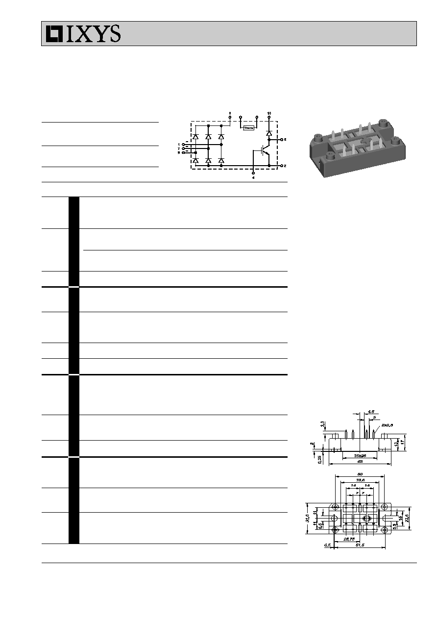
Dimensions in mm (1 mm = 0.0394")
VUB 71
749
Data according to IEC 60747
IXYS reserves the right to change limits, test conditions and dimensions.
V
RRM
= 1200-1600 V
I
dAVM
= 70 A
Three Phase Rectifier Bridge
with IGBT and Fast Recovery Diode
for Braking System
1 2
4 5
6
7
9 10
© 2000 IXYS All rights reserved
2 - 2
VUB 71
I
R
V
R
= V
RRM
,
T
VJ
= 25
°
C
0.2
mA
V
R
= 800 V, T
VJ
=150
°
C
4
6
mA
V
F
I
F
= 12 A,
T
VJ
= 25
°
C
2.7
V
V
T0
For power-loss calculations only
1.65
V
r
T
T
VJ
= 150
°
C
46
m
W
I
RM
I
F
= 25 A,
-di
F
/dt = 100 A/
m
s
6.5
7
A
V
R
= 100 V
t
rr
I
F
= 1 A,
-di
F
/dt = 100 A/
m
s
50
70
ns
V
R
= 30 V
R
thJH
3.12 K/W
R
25
Siemens Typ S 891/2,2k/+9
2,2
k
W
d
S
Creep distance on surface
12.7 mm
d
A
Strike distance in air
9.4 mm
a
Maximum allowable acceleration
50 m/s
2
Symbol
Test Conditions
Characteristic Values
(T
VJ
= 25
°
C, unless otherwise specified)
min.
typ.
max.
Rectifier Diodes
V
BR(CES)
V
GS
= 0 V, I
C
= 3 mA
1200
V
V
GE(th)
I
C
= 10 mA
5
8
V
I
GES
V
GE
=
±
20 V
500
nA
I
CES
T
VJ
=
25
°
C,
V
CE
= V
CES
700
m
A
T
VJ
=
125
°
C, V
CE
= 0.8 V
CES
1.5
mA
V
CEsat
V
GE
= 15 V, I
C
= 25 A
2.9
V
t
SC
V
GE
= 15 V, V
CE
= 600 V, T
VJ
=
125
°
C,
10
m
s
(SCSOA)
R
G
= 22
W
, non repetitive
RBSOA
V
GE
= 15 V, V
CE
= 800 V, T
VJ
=
125
°
C,
50
A
R
G
= 22
W
, Clamped Inductive load, L = 100
m
H
C
ies
V
CE
= 25 V, f = 1 MHz, V
GE
= 0 V
4.5
nF
t
d(on)
300
ns
t
d(off)
350
ns
t
fi
1600
ns
E
on
6
mJ
E
off
8
mJ
R
thJH
0.8 K/W
I
R
V
R
= V
RRM
,
T
VJ
= 25
°
C
0.1
mA
V
R
= V
RRM
,
T
VJ
= 150
°
C
3
mA
V
F
I
F
= 25 A,
T
VJ
= 25
°
C
1.3
V
V
T0
For power-loss calculations only
0.85
V
r
T
T
VJ
= 150
°
C
8.5
m
W
R
thJH
per diode
1.42 K/W
Rectifier Diodes
Fast Recovery Diode
V
CE
= 600 V, I
C
= 25 A
V
GE
= 15 V, R
G
= 22
W
Inductive load; L = 100
m
H
T
VJ
=
125
°
C
IGBT
Module
NTC
749