IXYS Corporation
3540 Bassett Street; Santa Clara, CA 95054
Tel: 408-982-0700; Fax: 408-496-0670
IXYS Semiconductor GmbH
POB 1180; D-68619; Lampertheim, Germany
Tel: +49-6206-5030; Fax: +49-6206-503627
Symbol
Test Conditions
Maximum Ratings
V
CES
T
J
= 25°C to 150°C
1200
V
V
CGR
T
J
= 25°C to 150°C; R
GE
= 1 M
1200
V
V
GES
Continuous
±20
V
V
GEM
Transient
±30
V
I
C25
T
C
= 25°C
30
A
I
C90
T
C
= 90°C
15
A
I
CM
T
C
= 25°C, 1 ms
60
A
SSOA
V
GE
= 15 V, T
J
= 125°C, R
G
= 82
I
CM
= 30
A
(RBSOA)
Clamped inductive load, L = 100 µH
@ 0.8 V
CES
t
sc
T
J
= 125şC, V
CE
= 720 V; V
GE
= 15V, R
G
= 82
5
µs
P
C
T
C
= 25°C
150
W
T
J
-55 ... +150
°C
T
JM
150
°C
T
STG
-55 ... +150
°C
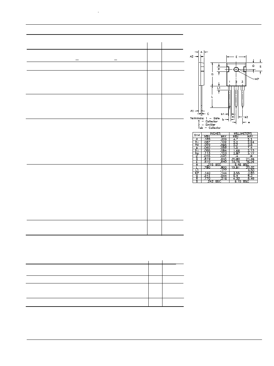
M
d
Mounting torque
1.15/10 Nm/lb-in.
.
Weight
6
g
Max. Lead Temperature for
300
°C
Soldering (1.6mm from case for 10s)
IGBT with Diode
"S" Series - Improved SCSOA Capability
IXSH15N120AU1
Features
· High frequency IGBT with guaranteed
Short Circuit SOA capability.
· IGBT with anti-parallel diode in one
package
· 2
nd
generation HDMOS
TM
process
Low V
CE(sat)
- for minimum on-state conduction
losses
· MOS Gate turn-on
- drive simplicity
Applications
· AC motor speed control
· DC servo and robot drives
· Uninterruptible power supplies
(UPS)
· Switched-mode and resonant-mode
power supplies
· DC choppers
Advantages
· Saves space (two devices in one
package)
· Easy to mount (isolated mounting hole)
· Reduces assembly time and cost
· Operates cooler
· Easier to assemble
E
G
C
C
E
G
TO-247AD
I
C25
=
30 A
V
CES
= 1200 V
V
CE(sat)
= 4.0 V
PRELIMINARY DATA SHEET
94522B(6/95)
© 1994 IXYS Corporation. All rights reserved.
Symbol
Test Conditions
Characteristic Values
(T
J
= 25°C unless otherwise specified)
Min.
Typ. Max.
BV
CES
I
C
= 4.0 mA, V
GE
= 0 V
1200
V
V
GE(th)
I
C
= 1.5 mA, V
CE
= V
GE
4
8
V
I
CES
V
CE
= 0.8 V
CES
, V
GE
= 0 V
T
J
= 25°C
500 µA
Note 2
T
J
= 125°C
8 mA
I
GES
V
CE
= 0 V, V
GE
= ±20 V
+ 100 nA
V
CE(sat)
I
C
= I
C90
, V
GE
= 15 V
4.0
V
IXYS Corporation
3540 Bassett Street; Santa Clara, CA 95054
Tel: 408-982-0700; Fax: 408-496-0670
IXYS Semiconductor GmbH
POB 1180; D-68619; Lampertheim, Germany
Tel: +49-6206-5030; Fax: +49-6206-503627
g
fs
I
C
= I
C90
,
V
CE
= 10 V,
6
7
S
Pulse test, t < 300 µs, duty cycle
< 2 %
I
C(on)
V
GE
= 15V, V
CE
= 10 V
65
A
C
ies
V
CE
= 25 V, V
GE
= 0 V, f = 1 MHz
1800
pF
C
oes
160
pF
C
res
45
pF
Q
g
I
C
= I
c90
, V
GE
= 15 V, V
CE
= 0.5 V
CES
75
nC
Q
ge
20
nC
Q
gc
35
nC
t
d(on)
Inductive load, T
J
= 25°C
100
ns
t
ri
I
C
= I
C90
, V
GE
= 15 V, L = 100µH
200
ns
t
d(off)
R
G
= 82
, V
CLAMP
= 0.8 V
CES
450
ns
t
fi
Note 1
600
ns
t
c
750
ns
E
off
5.4
mJ
t
d(on)
Inductive load, T
J
= 125°C
100
ns
t
ri
I
C
= I
C90,
V
GE
= 15 V, L = 100µH
200
ns
E
(on)
R
G
= 82
TBD
mJ
t
d(off)
V
CLAMP
= 0.8 V
CES
ns
t
fi
Note 1
900
ns
t
c
1200
ns
E
off
14.5
mJ
R
thJC
0.83 K/W
R
thCK
0.25
K/W
Reverse Diode (FRED)
Characteristic Values
(TJ = 25şC unless otherwise specified)
Min. Typ. Max.
V
F
I
F
= I
C90
, V
GE
= 0V
2.3
V
Pulse test, t< 300 µs, duty cycle < 2%
T
J
= 125şC
2.1
t
rr
I
F
= 1A; di/dt = -100A/µs; V
R
= 30V;
T
J
= 25şC
40
60
ns
I
RM
I
F
= I
C90
, V
GE
= 0V, -di
F
/dt = 240 A/µs
16
18
A
t
rr
T
J
= 100şC, V
R
= 540V
300
ns
R
thJC
1.0 K/W
Notes:
1) Switching times may increase for V
CE
(Clamp) > 0.8 V
CES
, higher T
J
or R
G
values.
2) Device must be heatsunk for high temperature leakage current measurements to avoid thermal runaway.
IXYS reserves the right to change limits, test conditions and dimensions.
Symbol
Test Conditions
Characteristic Values
(T
J
= 25°C unless otherwise specified)
Min Typ.
Max.
IXSH15N120AU1
TO-247AD (IXSH)