SD6000C..R SERIES
STANDARD RECOVERY DIODES
Hockey Puk Version
6690A
1
Bulletin I2035 rev. B 04/00
www.irf.com
Features
Wide current range
High voltage ratings up to 2400V
High surge current capabilities
Diffused junction
Hockey Puk version
Case style B-44 (R-PUK)
Typical Applications
Converters
Power supplies
High power drives
Auxiliary system supplies for traction applications
Major Ratings and Characteristics
I
F(AV)
6690
A
@ T
hs
55
°C
I
F(RMS)
11150
A
@ T
hs
25
°C
I
FSM
@
50Hz
76400
A
@ 60Hz
80000
A
I
2
t
@
50Hz
29200
KA
2
s
@ 60Hz
26650
KA
2
s
V
RRM
range
1200 to 2400
V
T
J
- 40 to 175
°C
Parameters
SD6000C..R
Units
case style B-44 (R-PUK)
SD6000C..R Series
2
Bulletin I2035 rev. B 04/00
www.irf.com
Voltage
V
RRM
, maximum repetitive
V
RSM
, maximum non-
I
RRM
max.
Type number
Code
peak reverse voltage
repetitive peak rev. voltage
@ T
J
= 175°C
V
V
mA
12
1200
1300
16
1600
1700
20
2000
2100
24
2400
2500
ELECTRICAL SPECIFICATIONS
Voltage Ratings
I
F(AV)
Max. average forward current
6690 (3520)
A
180° conduction, half sine wave
@ Heatsink temperature
55 (85)
°C
Double side (single side) cooled
I
F(RMS)
Max. RMS forward current
11150
A
@ 25°C heatsink temperature double side cooled
I
FSM
Max. peak, one-cycle forward,
76400
t = 10ms
No voltage
non-repetitive surge current
80000
t = 8.3ms
reapplied
64250
t = 10ms
100% V
RRM
67280
t = 8.3ms
reapplied
Sinusoidal halfwave,
I
2
t
Maximum I
2
t for fusing
29200
t = 10ms
No voltage
Initial T
J
= T
J
max.
26650
t = 8.3ms
reapplied
20640
t = 10ms
100% V
RRM
18850
t = 8.3ms
reapplied
I
2
t
Maximum I
2
t for fusing
292000
KA
2
s
t = 0.1 to 10ms, no voltage reapplied
V
F(TO)1
Low level value of threshold
voltage
V
F(TO)2
High level value of threshold
voltage
r
f
1
Low level value of forward
slope resistance
r
f
2
High level value of forward
slope resistance
V
FM
Max. forward voltage drop
1.22
V
I
pk
= 9000A, T
J
= T
J
max, t
p
= 10ms sinusoidal wave
A
KA
2
s
0.727
(16.7% x
x I
F(AV)
< I <
x I
F(AV)
), T
J
= T
J
max.
Parameter
SD6000C..R
Units
Conditions
Forward Conduction
V
m
0.055
(16.7% x
x I
F(AV)
< I <
x I
F(AV)
), T
J
= T
J
max.
1.350
(I >
x I
F(AV)
),T
J
= T
J
max.
0.027
(I >
x I
F(AV)
),T
J
= T
J
max.
SD6000C..R
100
SD6000C..R Series
3
Bulletin I2035 rev. B 04/00
www.irf.com
R
thJ-hs
Conduction
(The following table shows the increment of thermal resistence R
thJ-hs
when devices operate at different conduction angles than DC)
Ordering Information Table
1
-
Diode
2
-
Essential part number
3
-
0 = Standard recovery
4
-
C = Ceramic Puk
5
-
Voltage code: code x 100 = V
RRM
(see Voltage Ratings Table)
6
-
R = Puk Case B-44 (R-PUK)
1
2
3
4
5
6
Device Code
SD 600
0
C
24
R
Sinusoidal conduction Rectangular conduction
Conduction angle
Units
Conditions
Single Side Double Side Single Side Double Side
180°
0.0009
0.0010
0.0006
0.0006
120°
0.0010
0.0011
0.0010
0.0010
90°
0.0013
0.0013
0.0014
0.0014
K/W
T
J
= T
J
max.
60°
0.0019
0.0019
0.0020
0.0020
30°
0.0033
0.0033
0.0034
0.0034
T
J
Max. junction operating temperature range
-40 to 175
T
stg
Max. storage temperature range
-55 to 200
R
thJ-hs
Max. thermal resistance, junction
0.02
DC operation single side cooled
to heatsink
0.01
DC operation double side cooled
F
Mounting force, ± 10%
39200
N
(4000)
(Kg)
wt
Approximate weight
1590
g
Case style
B-44 (R-PUK)
See Outline Table
Parameter
SD6000C..R
Units
Conditions
Thermal and Mechanical Specifications
K/W
°C
SD6000C..R Series
4
Bulletin I2035 rev. B 04/00
www.irf.com
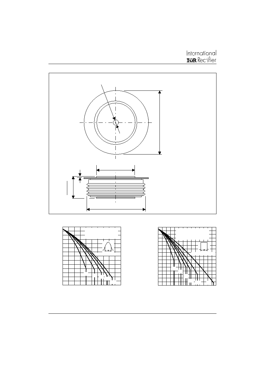
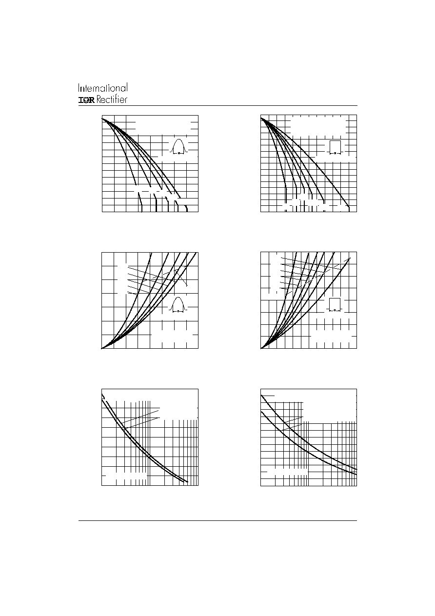
Fig. 1 - Current Ratings Characteristics
Outline Table
Fig. 2 - Current Ratings Characteristics
40
60
80
1 00
1 20
1 40
1 60
1 80
0
10 0 0
2 0 00
3 00 0
4 0 00
5 00 0
30
60
90
120
180
A vera g e Forw ard C urre n t (A)
M
a
x
i
mu
m
A
l
l
o
w
a
b
l
e
H
e
a
t
s
i
n
k
T
e
mp
e
r
a
t
u
r
e
(
C
)
C o n d uc tio n A ngle
SD 6000C ..R Serie s
(Sin g le Sid e C oole d )
R (D C ) = 0.02 K /W
th J -hs
20
40
60
80
1 0 0
1 2 0
1 4 0
1 6 0
1 8 0
0
10 0 0 2 00 0 30 0 0 40 0 0 50 0 0 60 00 70 0 0
30
60
90
180
D C
120
A ve rag e Forw ard C urre n t (A)
M
a
x
i
m
u
m
A
l
l
o
w
a
bl
e
He
ats
i
n
k
T
e
m
p
e
r
at
u
r
e
(
C
)
C o nd uc tion P e rio d
SD 6000C ..R Se rie s
(Sing le Sid e C oole d)
R (D C ) = 0.02 K/ W
th J-hs
3.5 (0.14) DIA. NOM. x
2.5 (0.10) DEEP MIN. BOTH ENDS
11
1
(
4
.
3
7)
D
I
A
.
M
A
X
.
TWO PLACES
73.2 (2.88) DIA. MAX.
100.5 (3.96) DIA. MAX.
3
7
.2
(
1
.4
6
)
3
6
.2
(1
.4
3
)
0.8 (0.03) MIN.
BOTH ENDS
Case Style B-44
All dimensions in millimeters (inches)
Quote between upper and lower
pole pieces has to be considered
after application of Mounting Force
(see Thermal and Mechanical
Specification)
SD6000C..R Series
5
Bulletin I2035 rev. B 04/00
www.irf.com
Fig. 3 - Current Ratings Characteristics
Fig. 4 - Current Ratings Characteristics
Fig. 5 - Forward Power Loss Characteristics
Fig. 6 - Forward Power Loss Characteristics
40
60
80
1 0 0
1 2 0
1 4 0
1 6 0
1 8 0
0
2 0 0 0
4 0 0 0
6 0 00
8 0 0 0
30
60
90
120
180
A ve ra g e Forw a rd C urre n t (A)
M
a
x
i
m
u
m A
l
l
o
w
a
b
l
e
H
e
a
t
s
i
n
k
T
e
mp
e
r
a
t
u
r
e
(
C
)
C o nd uc tion A ng le
SD 6000C ..R Se rie s
(D oub le Sid e C ooled )
R (D C ) = 0.01 K/ W
th J-hs
2 0
4 0
6 0
8 0
1 00
1 20
1 40
1 60
1 80
0
2 0 00
40 0 0
60 0 0
8 0 00 1 00 00 12 0 00
30
60
90
180
D C
120
A ve rag e Forw ard C urre n t (A)
M
a
x
i
m
u
m
Al
l
o
w
a
b
l
e H
e
a
t
s
i
nk T
e
m
p
er
a
t
u
r
e (
C
)
C o nd uctio n P erio d
SD 6000C ..R Se rie s
(D o ub le Sid e C oo le d )
R (D C ) = 0.01 K/ W
th J-hs
0
2 0 00
4 0 00
6 0 00
8 0 00
10 0 00
12 0 00
14 0 00
16 0 00
0
2 0 00
4 0 00
6 00 0
80 0 0 1 00 0 0 12 0 00
D C
180
120
90
60
30
A vera g e Forw a rd C urren t (A)
RM S Lim it
M
a
x
i
m
u
m
A
v
er
a
g
e F
o
r
w
a
r
d
P
o
w
e
r
Lo
s
s
(W
)
C o nd uc tion P e rio d
SD 6000C ..R Serie s
T = 175 C
J
0
2 0 0 0
4 0 0 0
6 0 0 0
8 0 0 0
1 0 0 0 0
1 2 0 0 0
1 4 0 0 0
0
2 0 0 0
4 0 0 0
60 0 0
8 0 0 0
180
120
90
60
30
A ve ra g e Forw a rd C u rren t (A )
M
a
x
i
mu
m A
v
e
r
a
g
e
F
o
r
w
a
r
d
P
o
we
r
L
o
s
s
(
W
)
R M S Lim it
C o nd uc tio n A ngle
SD 6000C ..R Se rie s
T = 175 C
J
2 00 00
3 00 00
4 00 00
5 00 00
6 00 00
7 00 00
1
10
10 0
Nu m b e r O f E q ua l A m p litud e H a lf C y cle C urre nt P u lses (N )
P
e
a
k
H
a
l
f
S
i
n
e
W
a
v
e
F
o
rw
a
r
d
C
u
rr
e
n
t
(
A
)
SD 6000C ..R S erie s
In itia l T = 175 C
@ 60 H z 0.0083 s
@ 50 H z 0.0100 s
J
At A n y Rate d Lo ad C on dition An d W ith
Ra ted V A pp lie d Follow in g Surg e .
RRM
1 0 0 00
2 0 0 00
3 0 0 00
4 0 0 00
5 0 0 00
6 0 0 00
7 0 0 00
8 0 0 00
0 .0 1
0 .1
1
Pulse T ra in D ura tion (s)
P
e
ak
Ha
l
f
S
i
n
e
W
a
v
e
F
o
r
w
ar
d
C
u
r
r
e
n
t
(
A
)
V e rsus Pulse Train D uration. C on trol
SD 6000C ..R Se rie s
In itia l T = 175 C
No V oltag e Re app lied
Rate d V Re ap plie d
RRM
J
M axim um Non Re p etitive Surg e C urre n t
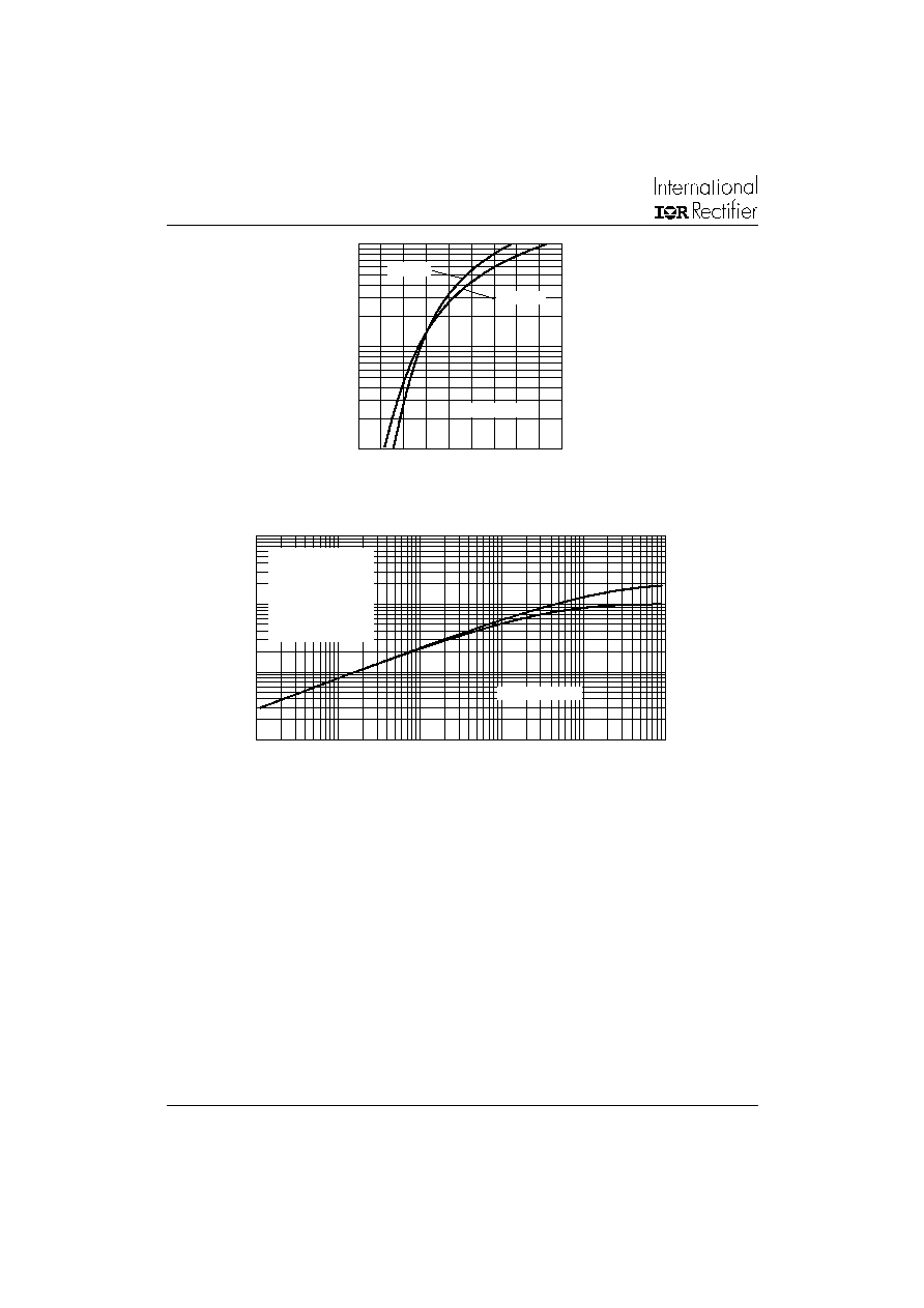
Fig. 7 - Maximum Non-Repetitive Surge Current
Single and Double Side Cooled
Fig. 8 - Maximum Non-Repetitive Surge Current
Single and Double Side Cooled
SD6000C..R Series
6
Bulletin I2035 rev. B 04/00
www.irf.com
Fig. 10 - Thermal Impedance Z
thJ-hs
Characteristics
Fig. 9 - Forward Voltage Drop Characteristics
1 00 0
10 0 0 0
10 00 0 0
0
0 .5
1
1 .5
2
2.5
3
3.5
4
4.5
T = 25 C
J
In sta n ta n eous Forw a rd V olta g e (V )
In
s
t
a
n
t
a
n
e
o
u
s
F
o
r
w
a
r
d
C
u
r
r
e
n
t
(
A
)
T = 175 C
J
SD 6000C ..R Se rie s
0.0 001
0 .001
0.0 1
0.1
0.0 01
0.01
0 .1
1
10
1 00
Square W ave P ulse D uration (s)
th
J
-
h
s
T
r
a
n
s
i
e
n
t
Th
e
r
m
a
l
I
m
p
e
d
a
n
c
e
Z
(
K
/
W
)
SD 6000C ..R Series
Ste ady State V alue
R = 0.02 K /W
(Sing le Side C o oled)
R = 0.01 K /W
(D o uble Side C ooled)
(D C O peration )
thJ-hs
th J-hs