3500 A
FAST RECOVERY DIODES
Preliminary Data Sheets I2098
1
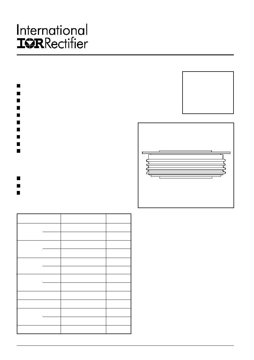
SD3553C..S20R SERIES
Hockey Puk Version
Features
High power FAST rectifier diode series
2.0 µs recovery time
High voltage ratings up to 2500 V
High current capability
Optimized turn on and turn off characteristics
Low forward recovery
Fast and soft reverse recovery
Press-puk encapsulation
Case style B-44 (R-PUK)
Maximum junction temperature 125°C
case style B-44 (R-PUK)
Typical Applications
Snubber diode for GTO
High voltage free-wheeling diode
Fast recovery rectifier applications
Major Ratings and Characteristics
Parameters
SD3553C..S20R
Units
I
F(AV)
3500
A
@ T
hs
55
°C
I
F(RMS)
6540
A
@ T
hs
25
°C
I
FSM
@ 50Hz
47
KA
@ 60Hz
50
KA
I
2
t
@ 50Hz
11045
KA
2
s
@ 60Hz
10375
KA
2
s
I
2
t
110450
KA
2
s
V
DRM
/V
RRM
range
1600 to 2500
V
t
rr
2.0
µs
@ T
J
25
°C
T
J
range
- 40 to 150
°C
SD3553C..S20R Series
2
Preliminary Data Sheets I2098
ELECTRICAL SPECIFICATIONS
Voltage Ratings
Voltage
V
RRM
, maximum repetitive
V
RSM
, maximum non-
I
RRM
max.
Type number
Code
peak reverse voltage
repetitive peak rev. voltage
@ T
J
= 150°c
V
V
mA
16
1600
1700
SD3553C..S20R
20
2000
2100
100
25
2500
2600
I
F(AV)
Maximum average forward current
3500 (1690)
A
180° conduction, half sine wave
@ Heatsink temperature
55 (85)
°C
Double side (single side) cooled
I
F(RMS)
Maximum RMS forward current
6540
A
@ 25°C heatsink temp. double side cooled
I
FSM
Maximum peak, one-cycle forward,
47.0
KA
t = 10ms
No voltage
non-repetitive surge current
50.0
t = 8.3ms reapplied
40.2
t = 10ms
100% V
RRM
42.6
t = 8.3ms reapplied
Sinusoidal half wave,
I
2
t
Maximum I
2
t for fusing
11045
KA
2
s t = 10ms
No voltage Initial T
J
= T
J
max.
10375
t = 8.3ms reapplied
8080
t = 10ms
50% V
RRM
7531
t = 8.3ms reapplied
I
2
t
Maximum I
2
t for fusing
110450
KA
2
s t = 0.1 to 10ms, no voltage reapplied
V
F(TO)1
Low level value of threshold voltage
1.082
V
(16.7% x
x I
F(AV)
< I <
x I
F(AV)
), T
J
= T
J
max.
V
F(TO)2
High level value of threshold voltage
0.160
(
x I
F(AV)
< I < 20 x
x I
F(AV)
), T
J
= T
J
max.
r
f1
Low level value of forward slope resistance
1.174
m
(16.7% x
x I
F(AV)
< I <
x I
F(AV)
), T
J
= T
J
max.
r
f2
High level value of forward slope resistance
0.152
(
x I
F(AV)
< I < 20 x
x I
F(AV)
), T
J
= T
J
max.
V
FM
Maximum forward voltage drop
2.04
V
T
J
= 150°C, I
FM
= 6000A
Parameter
SD3553C..R Units Conditions
Forward Conduction
Code
Test Conditions
Max. values @ T
J
= 150°C
T
J
= 25°C
Typical T
rr
I
pk
di/dt
V
r
t
rr
Q
rr
I
rr
@ 25% I
RRM
Square Pulse
@ 25% I
RRM
(µs)
(A)
(A/µs)
(V)
(µs)
(µC)
(A)
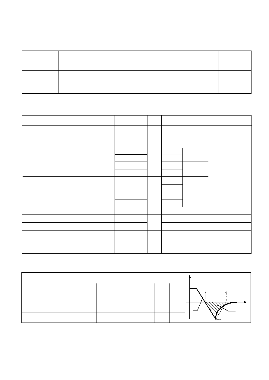
S20
2.0
1000
60
-50
5.50
1000
200
Recovery Characteristics
t
I
FM
t
rr
Q
rr
I
RM
(REC)
di
dt

SD3553C..S20R Series
3
Preliminary Data Sheets I2098
SD
355
3
C
25
S20
R
1
2
3
1
- Diode
2
- Essential part number
3
- 3 = Fast recovery
4
- C = Ceramic Puk
5
- Voltage code: Code x 100 = V
RRM
(See Voltage Ratings Table)
6
- t
rr
code (See Recovery Characteristics Table)
7
- K = Puk Case B-44 (R-PUK)
4
Device Code
Ordering Information Table
R
thJC
Conduction
(The following table shows the increment of thermal resistance R
thJC
when devices operate at different conduction angles than DC)
5
6
7
Sinusoidal conduction
Rectangular conduction
Single Side Double Side Single Side Double Side
Conduction angle
Units
Conditions
180°
0.0009
0.0010
0.0006
0.0006
120°
0.0010
0.0011
0.0010
0.0010
90°
0.0013
0.0013
0.0014
0.0014
K/W
T
J
= T
J
max.
60°
0.0019
0.0019
0.0020
0.0020
30°
0.0033
0.0033
0.0034
0.0034
T
J
Max. junction operating temperature range
- 40 to 150
°C
T
stg
Max. storage temperature range
- 40 to 150
R
thJ-hs
Max. thermal resistance, junction to
0.02
K/W
DC operation single side cooled
heatsink
0.01
DC operation double side cooled
F
Mounting force, ± 10%
39200
N
(4000)
(Kg)
wt
Approximate weight
1590
g
Case style
B-44 (R-PUK)
See outline table
Parameter
SD3553C..R Units Conditions
Thermal and Mechanical Specifications
SD3553C..S20R Series
4
Preliminary Data Sheets I2098
Data subject to change without notice.
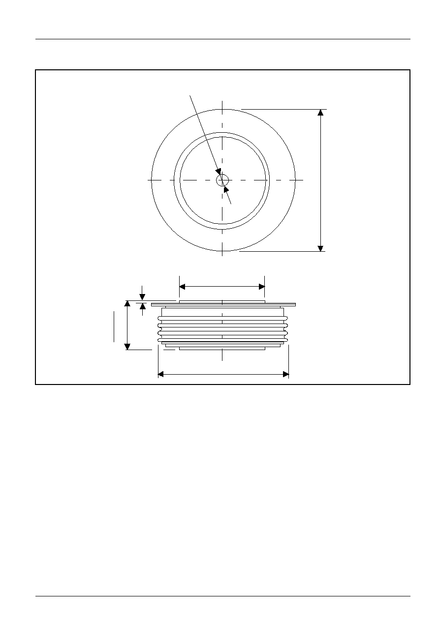
Outline Table
Case Style B-44 (R-PUK)
All dimensions in millimeters (inches)
3.5 (0.14) DIA. NOM. x
2.5 (0.10) DEEP MIN. BOTH ENDS
111
(
4
.
3
7
)
D
I
A
.
M
A
X
.
TWO PLACES
73.2 (2.88) DIA. MAX.
100.5 (3.96) DIA. MAX.
3
7
.2
(1
.4
6
)
3
6
.2
(1
.4
3
)
0.8 (0.03) MIN.
BOTH ENDS