Äîêóìåíòàöèÿ è îïèñàíèÿ www.docs.chipfind.ru
Preliminary Data Sheet No. PD60140J
··
··
·
Output power MOSFETs in half-bridge configuration
··
··
·
High side gate drive designed for bootstrap operation
··
··
·
Bootstrap diode integrated into package (HD type)
··
··
·
Tighter initial deadtime control
··
··
·
Low temperature coefficient deadtime
··
··
·
15.6V zener clamped Vcc for offline operation
··
··
·
Half-bridge output is out of phase with R
T
··
··
·
True micropower startup
··
··
·
Shutdown feature (1/6th V
CC
) on C
T
lead
··
··
·
Increased undervoltage lockout hysteresis (1Volt)
··
··
·
Lower power level-shifting circuit
··
··
·
Lower di/dt gate drive for better noise immunity
··
··
·
Excellent latch immunity on all inputs and outputs
··
··
·
ESD protection on all leads
··
··
·
Constant V
O
pulse width at startup
··
··
·
Heatsink package version (P2 type)
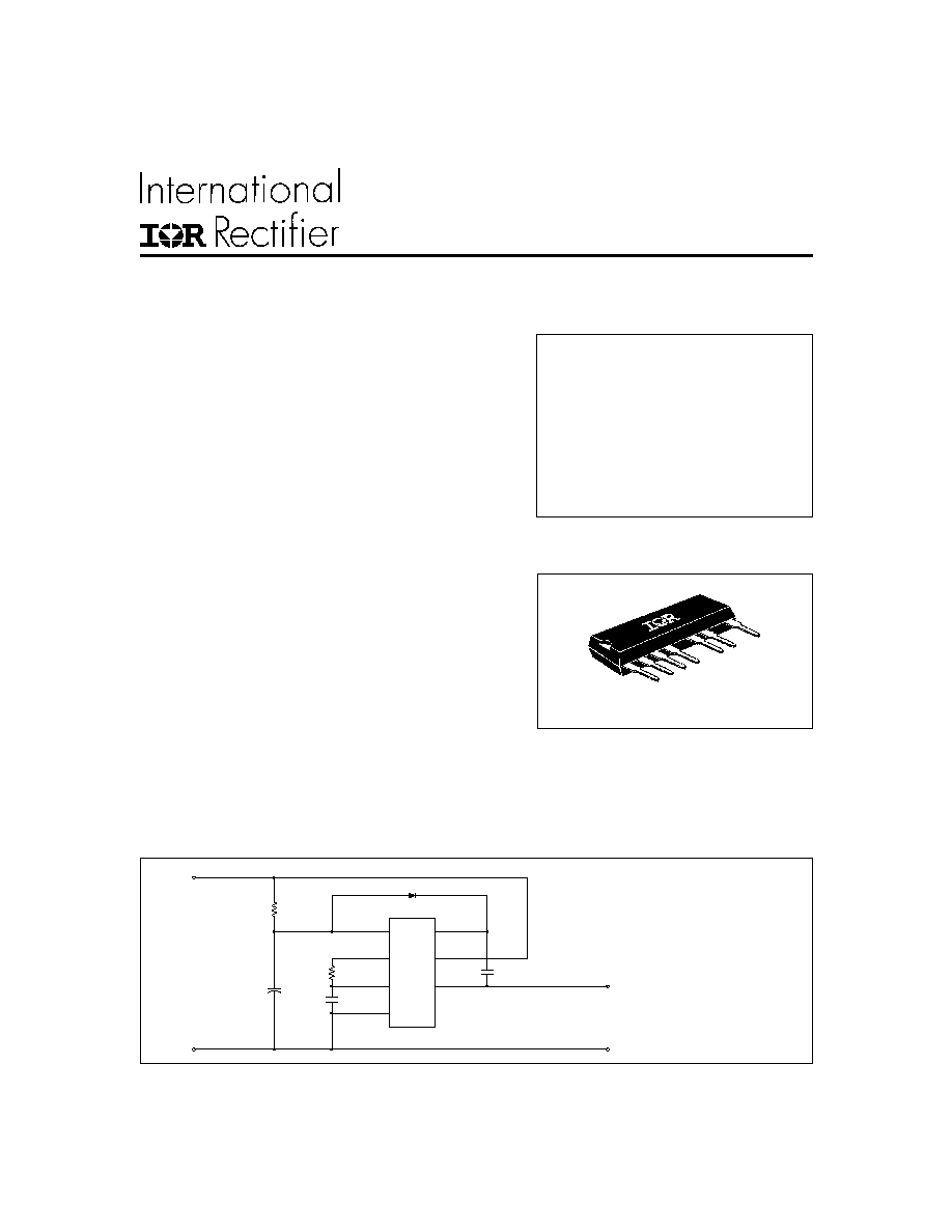
Description
The IR53H(D)420(-P2) are complete high voltage, high speed,
self-oscillating half-bridge circuits. Proprietary HVIC and latch
immune CMOS technologies, along with the HEXFET® power
MOSFET technology, enable ruggedized single package con-
struction. The front-end features a programmable oscillator
which functions similar to the CMOS 555 timer. The supply to
the control circuit has a zener clamp to simplify offline opera-
tion. The output features two HEXFETs in a half-bridge con-
figuration with an internally set deadtime designed for mini-
mum cross-conduction in the half-bridge. Propagation delays
SELF-OSCILLATING HALF BRIDGE
IR53H(D)420(-P2)
Package
Typical Connection
Product Summary
1
D 1
2
3
4
6
7
9
V c c
C O M
V O
V
IN
V
B
IR53H(D)420(-P2)
VIN
C O M
TO,
L O A D
H V D C B u s
R
T
C
T
R
T
C
T
External
Fast recovery diode D1 is not
required for HD type
VIN (max)
500V
Duty Cycle
50%
Deadtime (type.)
1.2
µ
s
Rds(on)
3.0
PD (TA = 25
o
C) 2.0W or 3.0W
Features
7 Pin Lead SIP
for the high and low side power MOSFETs
are matched to simplify use in 50% duty
cycle applications. The device can oper-
ate up to the V
IN
(max) rating.
2
IR53H(D)420(-P2)
NOTE 1:
This IC contains a zener clamp structure between V
CC
and COM which has a nominal breakdown voltage of 15.6V.
Please note that this supply pin should not be driven by a DC, low impedance power source greater than the V
CLAMP
specified in the Electrical Characteristics Section
Symbol
Definition
Minimum
Maximum
Units
V
IN
High voltage supply
- 0.3
500
V
B
High side floating supply
Vo - 0.3
Vo + 25
V
O
Half-bridge output
-0.3
V
IN
+ 0.3
V
RT
R
T
voltage
- 0.3
V
cc
+ 0.3
V
CT
C
T
voltage
- 0.3
V
cc
+ 0.3
Icc
Supply current (note 1)
--
25
I
RT
R
T
output current
- 5
5
dV/dt
Peak diode recovery
--
3.50
V/ns
P
D
Package power dissipation @ TA
+25°C
--
2
-P2
--
3
Rth
JA
Thermal resistance, junction to ambient
--
60
-P2
--
40
Rth
JC
Thermal resistance, junction to case -P2
--
20
(heatsink)
T
J
Junction temperature
-55
150
T
S
Storage temperature
-55
150
°C
T
L
Lead temperature (soldering, 10 seconds)
--
300
Absolute Maximum Ratings
Absolute maximum ratings indicate sustained limits beyond which damage to the device may occur. All volt-
age parameters are absolute voltages referenced to COM, unless stated otherwise. All currents are defined
positive into any lead. The thermal resistance and power dissipation ratings are measured under board
mounted and still air conditions.
V
o
C/W
W
mA
3
IR53H(D)420(-P2)
Symbol
Definition
Minimum
Maximum
Units
R
T
Timing resistor value
10
--
k
C
T
C
T
pin capacitor value
330
--
pF
Recommended Component Values
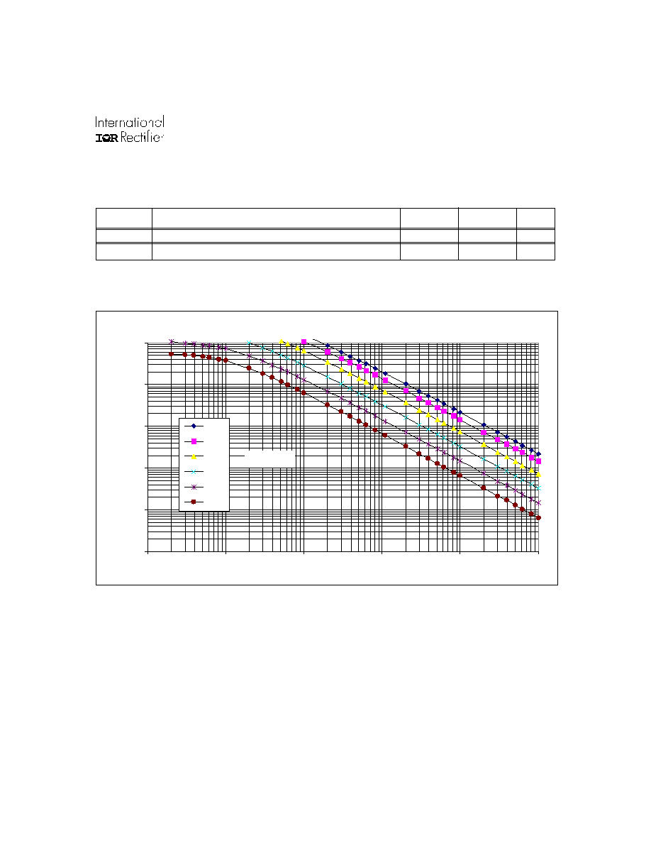
IR2153 RT vs Frequency
10
100
1000
10000
100000
1000000
10
100
1000
10000
100000
1000000
RT (ohms)
Frequency (Hz)
330pf
470pF
1nF
2.2nF
4.7nF
10nF
CT Values
IR53H(D)420(-P2) RT vs Frequency
4
IR53H(D)420(-P2)
Recommended Operating Conditions
The input/output logic timing diagram is shown in figure 1. For proper operation, the device should be used
within the recommended conditions.
NOTE 2:
Care should be taken to avoid switching conditions where the V
S
node flies inductively below ground by more than 5V.
NOTE 3:
Enough current should be supplied to the V
CC
lead of the IC to keep the internal 15.6V zener diode clamping the
voltage at this lead.
Symbol Definition
Minimum
Maximum
Units
V
B
High side floating supply absolute voltage
Vo + 10
Vo + Vclamp
V
IN
High voltage supply
--
500
V
O
Half-bridge output voltage
-3.0 (note 3)
500
I
D
Continuous drain current (TA = 25°C)
--
0.7
-P2
--
0.85
(TA = 85°C)
--
0.5
-P2
--
0.6
(TC = 25°C)
-P2
--
1.2
I
CC
Supply current
(note 3)
5
mA
T
A
Ambient temperature
-40
125
°C
V
A
Electrical Characteristics
V
BIAS
(V
CC
, V
BS
) = 12V, C
T
= 1 nF and T
A
= 25°C unless otherwise specified. The V
IN
, V
TH
and I
IN
parameters are
referenced to COM.
MOSFET Characteristics
Symbol Definition
Min. Typ. Max. Units T
est
C
onditions
trr
Reverse recovery time (MOSFET body diode)
--
240
--
Qrr
Reverse recovery charge (MOSFET body diode)
--
0.5
--
R
ds(on)
Static drain-to-source on resistance
--
3.0
--
V
SD
Diode forward voltage
--
0.8
--
V
Dynamic Characteristics
Symbol Definition
Min. Typ. Max. Units T
est
C
onditions
D
RT duty cycle
--
50
--
% fosc = 20 kHz
tsd
Shutdown propagation delay
--
660
--
nsec
µ
C
di/dt =
100
A/
µ
s
I
F
=700mA
5
IR53H(D)420(-P2)
Symbol Definition
Min.
Typ.
Max. Units Test Conditions
fosc
Oscillator frequency
19.4
20
20.6
R
T
= 36.9k
94
100
106
R
T
= 7.43k
d R
T
pin duty cycle
48
50
52
%
fo < 100kHz
I
CT
C
T
pin current
--
0.001
1.0
uA
I
CTUV
UV-mode C
T
pin pulldown current
0.30
0.70
1.2
mA
V
CC
= 7V
V
CT+
Upper C
T
ramp voltage threshold
--
8.0
--
V
CT-
Lower C
T
ramp voltage threshold
--
4.0
--
V
CTSD
C
T
voltage shutdown threshold
1.8
2.1
2.4
V
RT+
High-level R
T
output voltage, V
CC
- V
RT
--
10
50
I
RT
= 100
µ
A
--
100
300
I
RT
= 1mA
V
RT-
Low-level R
T
output voltage
--
10
50
I
RT
= 100
µ
A
--
100
300
I
RT
= 1mA
V
RTUV
UV-mode R
T
output voltage
--
0
100
V
CC
V
CCUV
-
V
RTSD
SD-Mode R
T
output voltage, V
CC
- V
RT
--
10
50
I
RT
= 100
µ
A,
V
CT
= 0V
--
10
300
I
RT
= 1mA,
V
CT
= 0V
V
mV
kHz
Floating Supply Characteristics
Oscillator I/O Characteristics
Symbol Definition
Min.
Typ.
Max. Units Test Conditions
I
QBSUV
Micropower startup V
BS
supply current
--
0
10
V
CC
V
CCUV
-
I
QBS
Quiescent VBS supply current
-- 30
50
V
BSMIN
Minimum required V
BS
voltage for proper
-- 4.0 5.0
V V
CC
=V
CCUV+
+ 0.1V
functionality from R
T
to HO
I
OS
Offset supply leakage current
--
--
50
µ
A
V
B
= V
S
= 600V
V
F
Bootstrap diode forward voltage (IR2153D)
0.5
--
1.0
V
I
F
= 250mA
µ
A
Electrical Characteristics
V
BIAS
(V
CC
, V
BS
) = 12V, C
T
= 1 nF and T
A
= 25°C unless otherwise specified. The V
IN
, V
TH
and I
IN
parameters are
referenced to COM.
Low Voltage Supply Characteristics
Symbol Definition
Min.
Typ. Max. Units Test Conditions
V
CCUV+
Rising V
CC
undervoltage lockout threshold
8.1
9.0 9.9
V
CCUV-
Falling V
CC
undervoltage lockout threshold
7.2
8.0 8.8
V
CCUVH
V
CC
undervoltage lockout Hysteresis
0.5
1.0
1.5
I
QCCUV
Micropower startup V
CC
supply current
--
75
150
V
CC
V
CCUV
-
I
QCC
Quiescent V
CC
supply current
--
500 950
V
CLAMP
V
CC
zener clamp voltage
14.4
15.6 16.8
V
I
CC
= 5mA
V
µ
A