Transmissive Optoschmitt Sensor
HOA2001
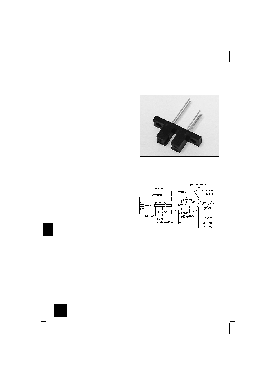
DESCRIPTION
FEATURES
Direct TTL interface
·
Buffer logic
·
0.060 in.(1.52 mm) dia. detector aperture
·
0.120 in.(3.05 mm) slot width
·
0.050 in.(1.27) offset pin circle detector eads
·
The HOA2001 consists of an infrared emitting diode
facing an Optoschmitt detector encased in a black
thermoplastic housing. The photodetector consists of a
photodiode, amplifier, voltage regulator, Schmitt trigger
and an NPN output transistor with 10 kě (nominal) pull-
up resistor. The buffer logic provides a high output
when the optical path is clear, and a low output when
the path is interrupted. The HOA2001 employs plastic
molded components. For additional component
information see SEP8506 and SDP8600.
Housing material is polyester. Housings are soluble in
chlorinated hydrocarbons and ketones. Recommended
cleaning agents are methanol and isopropanol.
DIM_062.ds4
INFRA-45.TIF
OUTLINE DIMENSIONS in inches (mm)
3 plc decimals
±0.010(0.25)
Tolerance
2 plc decimals
±0.020(0.51)
Honeywell reserves the right to make
changes in order to improve design and
supply the best products possible.
h
360
Transmissive Optoschmitt Sensor
HOA2001
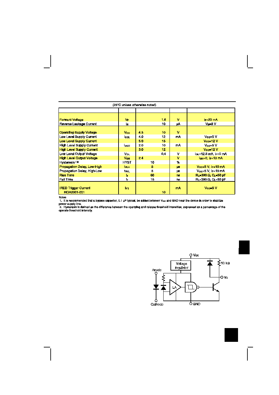
ELECTRICAL CHARACTERISTICS
UNITS
TEST CONDITIONS
MIN
PARAMETER
SYMBOL
TYP
MAX
IR EMITTER
DETECTOR
COUPLED CHARACTERISTICS
ABSOLUTE MAXIMUM RATINGS
(25ˇC Free-Air Temperature unless otherwise noted)
Operating Temperature Range
-40ˇC to 70ˇC
Storage Temperature Range
-40ˇC to 85ˇC
Soldering Temperature (5 sec)
240ˇC
IR EMITTER
Power Dissipation
100 mW [Ŕ]
Reverse Voltage
3 V
Continuous Forward Current
50 mA
DETECTOR
Supply Voltage
12 V [Á]
Output Sink Current
18 mA
Duration of Output
Short to VŮŮ or Ground
1.0 sec.
SCHEMATIC
Honeywell reserves the right to make
changes in order to improve design and
supply the best products possible.
h
361
Transmissive Optoschmitt Sensor
HOA2001
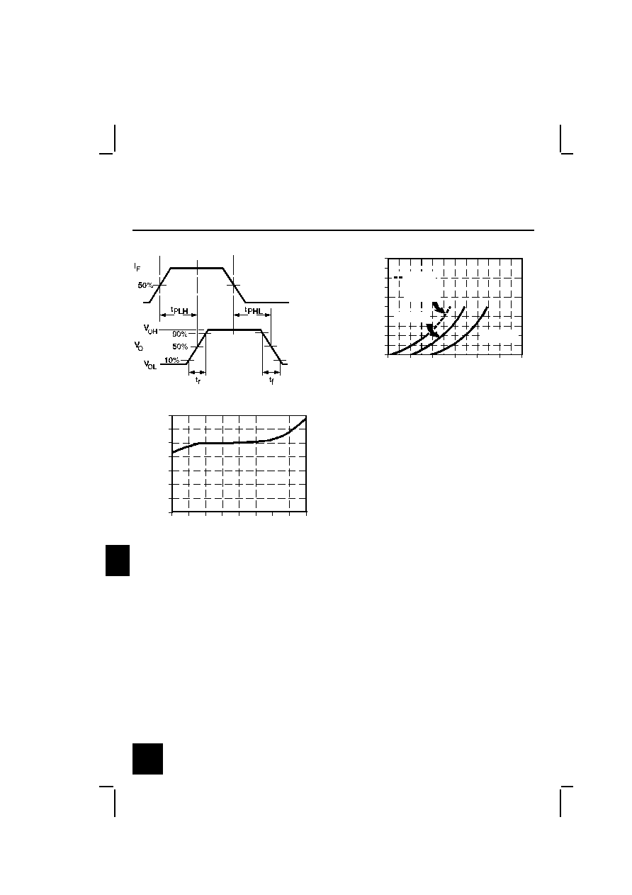
SWITCHING WAVEFORM
cir_013.cdr
IRED Forward Bias Characteristics
gra_073.ds4
Forward voltage - V
F
o
r
w
a
r
d
c
u
r
r
e
n
t
-
m
A
0
10
20
30
40
50
60
70
80
90
100
0.8
1.0
1.2
1.4
1.6
1.8
2.0
Pulsed
condition
T
A
= 80°C
T
A
= -40°C
T
A
= 25°C
Fig. 1
IRED Trigger Current vs Temperature
gra_098.ds4
Ambient temperature - °C
·
N
o
r
m
a
l
i
z
e
d
t
r
i
g
g
e
r
c
u
r
r
e
n
t
0.0
0.2
0.4
0.6
1.0
1.2
1.4
0.8
-75
0
50
75
125
-25
-50
25
100
Fig. 2
All Performance Curves Show Typical Values
Honeywell reserves the right to make
changes in order to improve design and
supply the best products possible.
h
362

Transmissive Optoschmitt Sensor
HOA2001
Honeywell reserves the right to make
changes in order to improve design and
supply the best products possible.
h
363