
2SC5225
Silicon NPN Epitaxial Transistor
ADE-208-393
1st. Edition
Application
·
Wide band video output amplifier for color CRT monitor.
·
High frequency high voltage amplifier.
·
High speed power switching.
·
Complementary pair with 2SA1960.
Features
·
High voltage large current operation.
V
CEO
= 80 V, I
C
= 300 mA
·
High f
T
.
f
T
= 1.4 GHz
·
Small output capacitance.
Cob = 3 pF

2SC5225
2
Outline
1. Emitter
2. Collector
3. Base
TO-92 (1)
3
2
1
Absolute Maximum Ratings (Ta = 25°C)
Item
Symbol
Ratings
Unit
Collector to base voltage
V
CBO
100
V
Collector to emitter voltage
V
CEO
80
V
Emitter to base voltage
V
EBO
3
V
Collector current
I
C
300
mA
Collector power dissipation
P
C
625
mW
Junction temperature
Tj
150
°
C
Storage temperature
Tstg
55 to +150
°
C
2SC5225
3
Electrical Characteristics (Ta = 25°C)
Item
Symbol
Min
Typ
Max
Unit
Test conditions
Collector to base breakdown
voltage
V
(BR)CBO
100
--
--
V
I
C
= 100
µ
A, I
E
= 0
Collector to emitter breakdown
voltage
V
(BR)CEO
80
--
--
V
I
C
= 1 mA, R
BE
=
Collector to base cutoff current
I
CBO
--
--
1
µ
A
V
CB
= 80 V, I
E
= 0
Emitter to base cutoff current
I
EBO
--
--
10
µ
A
V
EB
= 3 V, I
C
= 0
DC current transfer ratio
h
FE
20
70
--
V
CE
= 5 V, I
C
= 50 mA
Pulse test
Gain bandwidth product
f
T
1.2
1.4
--
GHz
V
CE
= 10 V, I
C
= 50 mA
Emitter input capacitance
Cib
--
13
19
pF
V
EB
= 0, I
C
= 0, f = 1 MHz
Collector output capacitance
Cob
--
3
4
pF
V
CB
= 10 V, I
E
= 0, f = 1 MHz
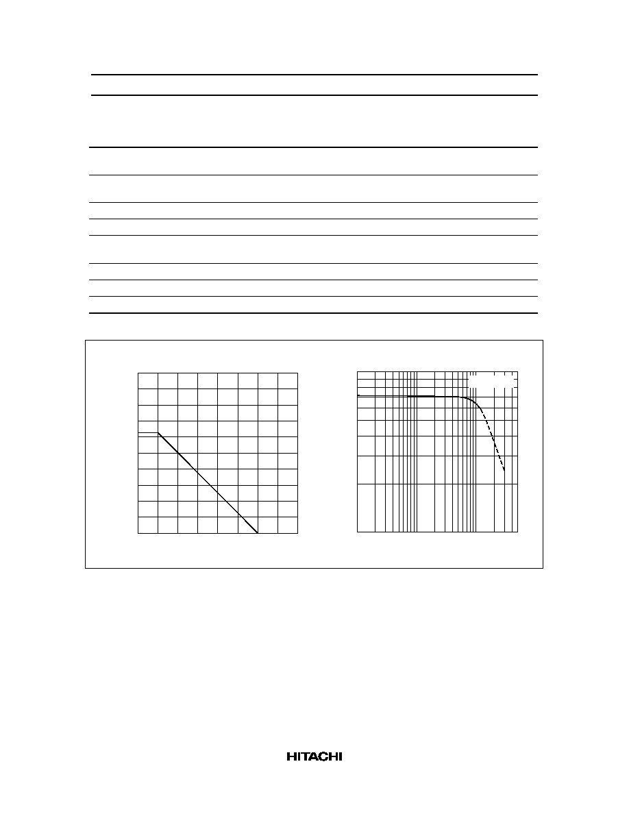
1000
800
600
400
200
0
50
100
150
200
Ambient Temperature Ta (
°
C)
Collector Power Dissipation Pc (mW)
Collector Power Dissipation Curve
100
1
2
5
10 20
50 100 200 500
10
20
50
V = 5V
CE
Collector Current I (mA)
C
DS Current Transfer Ratio h
FE
DC Current Transfer Ratio vs.
Collector Current
2SC5225
4
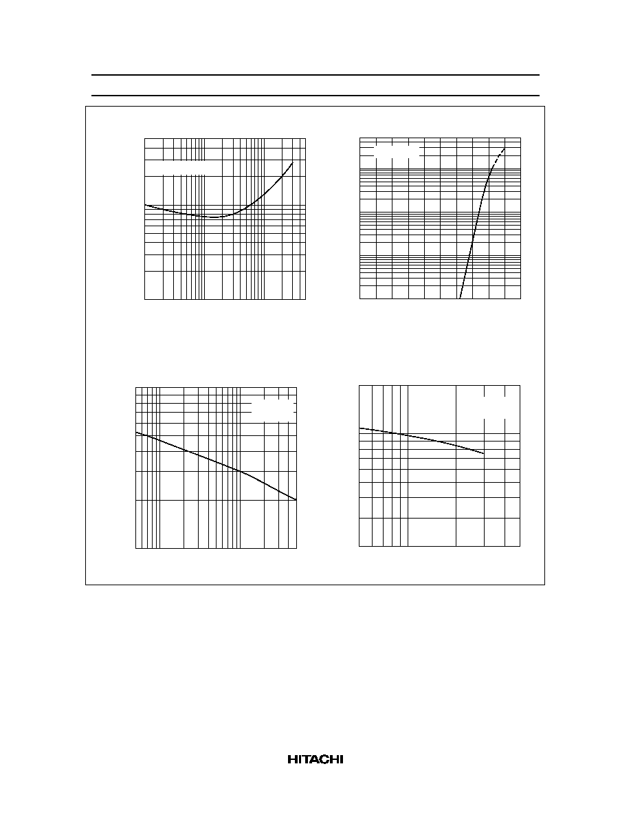
500
200
100
20
50
10
1
2
5
10 20
50 100 200 500
I / I = 10
C
B
Collector to Emitter Saturation Voltage
vs. Collector Current
Collector to Emitter Saturation Voltage
V (mV)
CE(sat)
Collector Current I (mA)
C
500
200
100
20
50
10
2
5
1
0.2
0.5
0.1
0
0.2
0.4
0.6
0.8
1.0
V = 5V
CE
Collector Current I (mA)
C
Collector Current vs.
Base to Emitter Voltage
Base to Emitter Voltage V (V)
BE
10
2
5
1
0.5
1
2
5
10
20
50
I = 0
f = 1 MHz
E
Collector Output Capacitance Cob (pF)
Collector to Base Voltage V (V)
CB
Collector Output Capacitance vs.
Collector to Base Voltage
0.5
20
10
5
2
1
2
5
I = 0
f = 1 MHz
C
Emitter Input Capacitance Cib (pF)
Emitter to Base Voltage V (V)
EB
Emitter Input Capacitance vs.
Emitter to Base Voltage

2SC5225
5
1.5
1.0
0.5
0
1
2
5
10
20
50
100
V = 10 V
CE
V = 5 V
CE
Collector Current I (mA)
C
Gain Bandwidth Product f (GHz)
T
Gain Bandwidth Product vs.
Collector Current