Notes:
(1) Test conditions: I
F
=0.5A, I
R
=1.0A, I
rr
=0.25A
(2) Measured at 1.0MHz and applied reverse voltage of 4.0 volts
Symbols
HER
101G
HER
102G
HER
103G
HER
104G
HER
105G
HER
106G
HER
107G
HER
108G
Units
Maximum repetitive peak reverse voltage
V
RRM
50
100
200
300
400
600
800
1000
Volts
Maximum RMS voltage
V
RMS
35
70
140
210
280
420
560
700
Volts
Maximum DC blocking voltage
V
DC
50
100
200
300
400
600
800
1000
Volts
Maximum average forward rectified current
0.375" (9.5mm) lead length at T
A
=50
I
(AV)
1.0
Amp
Peak forward surge current
8.3mS single half sine-wave superimposed
on rated load (MIL-STD-750D 4066 method)
I
FSM
30.0
Amps
Maximum instantaneous forward voltage at 1.0A DC
V
F
1.0
1.3
1.5
1.7
Volts
Maximum full load reverse current average, full cycle
0.375" (9.5mm) lead length at T
L
=55
I
R(AV)
100.0
A
Maximum DC reverse current T
A
=25
at rated DC blocking voltage
I
R
5.0
A
Typical reverse recovery time (Note 1)
T
rr
50.0
75.0
nS
Typical junction capacitance (Note 2)
C
J
15
12
F
Operating and storage temperature range
T
J
, T
STG
-65 to +150
Features
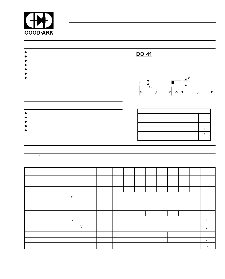
Mechanical Data
HER101G THRU HER108G
HIGH EFFICIENCY GLASS PASSIVATED RECTIFIER
Reverse Voltage -
50 to 1000 Volts
Forward Current -
1.0 Ampere
Low power loss, high efficiency
Low leakage
Low forward voltage
High current capability
High speed switching
High surge capability
High reliability
Case: Molded plastic
Epoxy: UL94V-0 rate flame retardant
Lead: MIL-STD-202E method 208C guaranteed
Mounting Position: Any
Weight: 0.012 ounce, 0.335 gram
Maximum Ratings and Electrical Characteristics
1
Ratings at 25 ambient temperature unless otherwise specified.
Single phase, half wave, 60Hz, resistive or inductive load.
For capacitive load, derate current by 20%.
DIMENSIONS
DIM
inches
mm
Note
Min.
Max.
Min.
Max.
A
0.165
0.205
4.2
5.2
B
0.079
0.106
2.0
2.7
C
0.028
0.034
0.71
0.86
D
1.000
-
25.40
-
