SMZJ3788 thru SMZJ3809B
Vishay Semiconductors
formerly General Semiconductor
Document Number 88402
www.vishay.com
09-Oct-02
1
Surface Mount
Power Voltage-Regulating Diodes
Zener Voltage 9.1 to 68V
Steady State Power 1.5W
Maximum Electrical Characteristics
Operating Junction and Storage Temperature Range: T
J
, T
STG
: 55°C to +150°C
Device
Nominal Zener
Test
Max. Zener Impedance
Max. Reverse
Max. Zener
Part Number
Marking
Voltage
Current
Leakage Current
Current
Current
Code
V
Z
at I
ZT
I
ZT
Z
ZT
at I
ZT
Z
ZK
at I
ZK
I
R
at V
R
I
ZM
(V)
(mA)
(
)
(
)
(mA)
(
µ
A)
(V)
(mA)
SMZJ3788A,B
VK,L
9.1
41.2
4.0
1000
0.50
50
7.0
140
SMZJ3789A,B
WA,B
10
37.5
5.0
1000
0.25
50
7.6
125
SMZJ3790A,B
WC,D
11
34.1
6.0
650
0.25
10
8.4
115
SMZJ3791A,B
WE,F
12
31.2
7.0
550
0.25
5.0
9.1
105
SMZJ3792A,B
WG,H
13
28.8
7.5
550
0.25
5.0
9.9
98
SMZJ3793A,B
WI,J
15
25.0
9.0
600
0.25
5.0
11.4
85
SMZJ3794A,B
WK,L
16
23.4
10.0
600
0.25
5.0
12.2
80
SMZJ3795A,B
XA,B
18
20.8
12.0
650
0.25
5.0
13.7
70
SMZJ3796A,B
XC,D
20
18.7
14.0
650
0.25
5.0
15.2
62
SMZJ3797A,B
XE,F
22
17.0
17.5
650
0.25
5.0
16.7
56
SMZJ3798A,B
XG,H
24
15.6
19.0
700
0.25
5.0
18.2
51
SMZJ3799A,B
XI,J
27
13.9
23.0
700
0.25
5.0
20.6
46
Notes: (1) Standard voltage tolerance is ±20%, suffix "A" denotes ±10% and suffix "B" denotes ±5%
(2) Maximum steady state power dissipation is 1.5W at T
L
= 75°C (See Fig. 1)
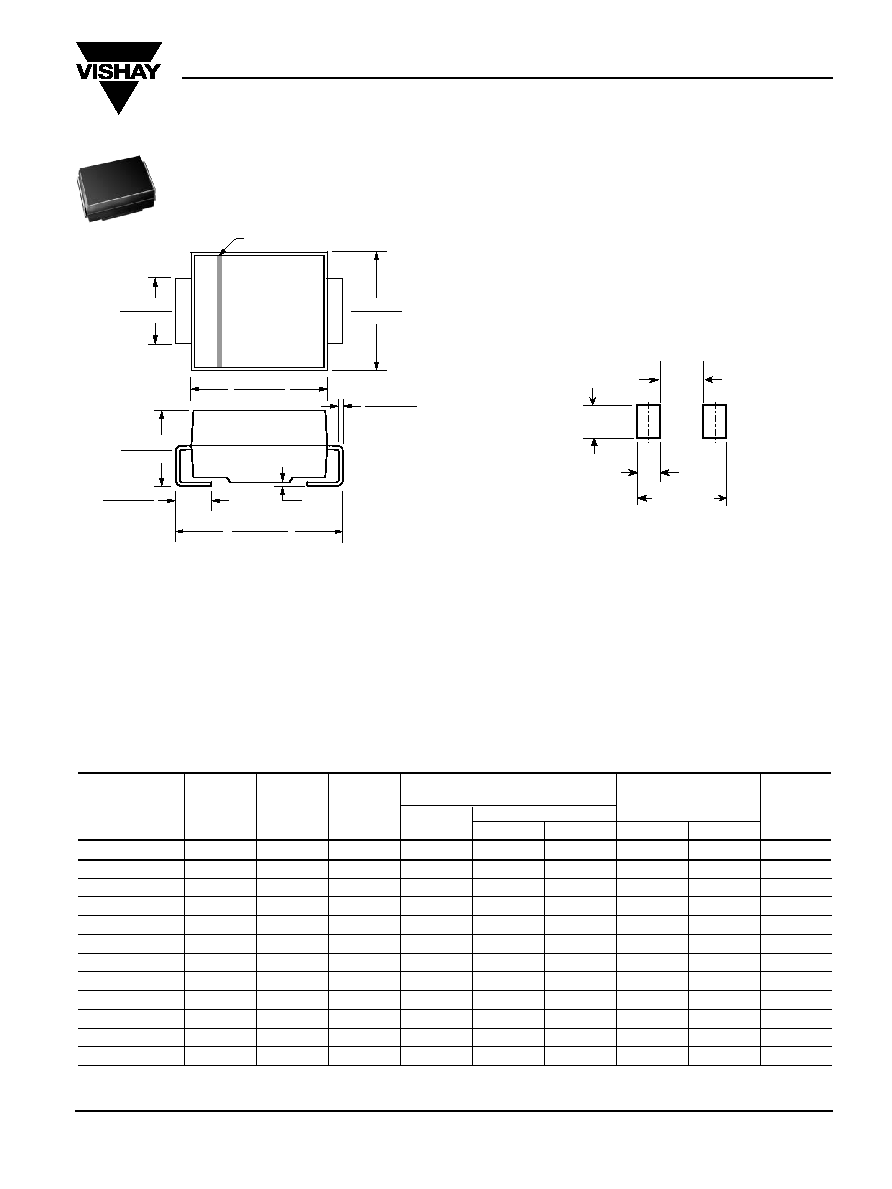
0.180 (4.57)
0.160 (4.06)
0.012 (0.305)
0.006 (0.152)
0.008
(0.203)
Max.
0.220 (5.59)
0.205 (5.21)
0.060 (1.52)
0.030 (0.76)
0.155 (3.94)
0.130 (3.30)
0.086 (2.20)
0.077 (1.95)
0.096 (2.44)
0.084 (2.13)
Cathode Band
Dimensions in inches
and (millimeters)
DO-214AA (SMBJ-Bend)
Features
· Plastic package has Underwriters Laboratory
Flammability Classificaion 94V-0
· For surface mounted applications
· Glass passivated chip junction
· Low Zener impedance
· Low regulation factor
· High temperature soldering guaranteed:
250°C/10 seconds at terminals
Mechanical Data
Case: JEDEC DO-214AA molded plastic over glass
passivated junction
Terminals: Solder plated, solderable per MIL-STD-750,
Method 2026
Polarity: Band denotes cathode
Mounting Position: Any Weight: 0.003 oz., 0.093 g
Packaging Codes Options (Antistatic):
51 2K per Bulk box, 20K/carton
52 750 per 7" plastic Reel (12mm tape), 15K/carton
5B 3.2K per 13" plastic Reel (12mm tape), 32K/carton
0.106 MAX
(2.69 MAX)
0.050 MIN
(1.27 MIN)
0.220 REF
0.083 MIN
(2.10 MIN)
Mounting Pad Layout
Extended V
oltage
Range

SMZJ3788 thru SMZJ3809B
Vishay Semiconductors
formerly General Semiconductor
www.vishay.com
Document Number 88402
2
09-Oct-02
Ratings and Characteristic Curves
(T
A
= 25°C unless otherwise noted)
Max. Electrical Characteristics (con't.)
Operating Junction and Storage Temperature Range: T
J
, T
STG
: 55°C to +150°C
Device
Nominal Zener
Test
Max. Zener Impedance
Max. Reverse
Max. Zener
Part Number
Marking
Voltage
Current
Leakage Current
Current
Current
Modified J-Bend
Code
V
Z
at I
ZT
I
ZT
Z
ZT
at I
ZT
Z
ZK
at I
ZK
I
R
at V
R
I
ZM
(V)
(mA)
(
)
(
)
(mA)
(
µ
A)
(V)
(mA)
SMZJ3800A,B
XK,L
30
12.5
26.0
750
0.25
5.0
22.8
41
SMZJ3801A,B
YA,B
33
11.4
33.0
800
0.25
5.0
25.1
38
SMZJ3802A,B
YC,D
36
10.4
38.0
850
0.25
5.0
27.4
35
SMZJ3803A,B
YE,F
39
9.6
45.0
900
0.25
5.0
29.7
31
SMZJ3804A,B
YG,H
43
8.7
53.0
950
0.25
5.0
32.7
28
SMZJ3805A,B
YI,J
47
8.0
67.0
1000
0.25
5.0
35.8
26
SMZJ3806A,B
YK,L
51
7.3
70.0
1100
0.25
5.0
38.8
24
SMZJ3807A,B
ZA,B
56
6.7
86.0
1300
0.25
5.0
42.6
22
SMZJ3808A,B
ZC,D
62
6.0
100.0
1500
0.25
5.0
47.1
20
SMZJ3809A,B
ZE,F
68
5.5
120.0
1700
0.25
5.0
51.7
18
Notes: (1) Standard voltage tolerance is ±20%, suffix "A" denotes ±10% and suffix "B" denotes ±5%
(2) Maximum steady state power dissipation is 1.5W at T
L
= 75°C (See Fig. 1)
0
100
10
1,000
1
100
500
10
0.5
Fig. 2 Typical Zener Impedance
Z
Z
-
-
Dynamic Impedance (
)
I
Z
-- Zener Test Current (mA)
0
2.0
1.5
1.0
25
50
75
100
125
150
175
Fig. 1 Maximum Continuous Power
Dissipation
P
M(A
V)
-
-
A
v
er
age P
o
w
er Dissipation (W)
T
L
-- Lead Temperature (
°
C)
Fig. 4 Typical Temperature
Coefficients
VZ
-
-
T
emper
ature Coefficient (mV/
°
C)
V
Z
-- Zener Voltage (V)
0.5
60H
Z
Resistive or
Inductive Load
P.C.B. Mounted on
0.31 x 0.31 x 0.08" (8 x 8 x 2mm)
Copper Pad Areas
T
J
= 25
°
C
I
Z
(rms) = 0.1I
Z
(DC)
V
Z
= 62V
V
Z
= 22V
V
Z
= 10V
2
100
200
10
100
10
Fig. 3 Typical Zener Impedance
Z
Z
-
-
Dynamic Impedance (
)
V
Z
-- Zener Voltage (V)
I
Z
(rms) = 0.1I
Z
(DC)
I
Z
= 1mA
I
Z
= 10mA
I
Z
= 20mA
100
10
100
10
Tested at Rated I
ZT