SYMBOL
MIN.
TYP.
MAX.
UNIT
Thermal Resistance
R
thJA
300
(1)
°C/W
Junction to Ambient Air
Forward Voltage
V
F
1.5
Volts
at I
F
= 200 mA
NOTES:
(1) Valid provided that leads at a distance of 3/8" from case are kept at ambient temperature.
FEATURES
Silicon Planar Power Zener Diodes
Standard Zener voltage tolerance is ±5% for
"B" suffix. Other tolerances are available upon
request.
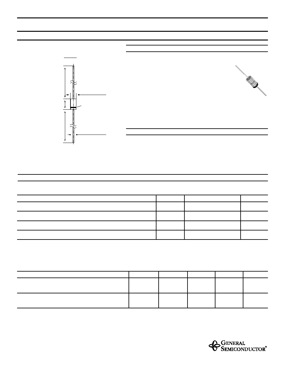
MECHANICAL DATA
Case: DO-35 Glass Case
Weight: approx. 0.13 g
MAXIMUM RATINGS
Ratings at 25°C ambient temperature unless otherwise specified.
1N957 THRU 1N978
ZENER DIODES
mi
n. 1.083 (
27.5)
mi
n. 1.083
(
2
7
.
5)
max
. .
150 (
3.8)
max.
Cathode
.020 (0.52)
Mark
max.
.079 (2.0)
DO-35
Dimensions are in inches and (millimeters)
1/6/98
SYMBOL
VALUE
UNIT
Zener Current (see Table "Characteristics")
Power Dissipation at T
L
= 75°C
P
tot
500
(1)
mW
Junction Temperature
T
j
175
°C
Storage Temperature Range
T
S
65 to +175
°C
NOTES:
(1) T
L
is measured 3/8" from body.
NEW PRODUCT
NEW PRODUCT
NEW PRODUCT

1N957 THRU 1N978
ELECTRICAL CHARACTERISTICS
Ratings at 25°C ambient temperature unless otherwise specified.
Type
Number
Nominal
Zener Voltage
V
Z
(3)
(Volts)
Test
Current
I
ZT
(mA)
Maximum Zener Impedance
(1)
Maximum
Regulator Current
I
ZM
(2)
(mA)
Maximum Reverse Current
I
R
Maximum
(
µ
A)
Test Voltage Vdc
(Volts)
Z
ZT
@ I
ZT
(
)
Z
ZK
@ I
ZK
(
)
I
ZK
(mA)
1N957B
6.8
18.5
4.5
700
1
47
150
5.2
1N958B
7.5
16.5
5.5
700
0.5
42
75
5.7
1N959B
8.2
15
6.5
700
0.5
38
50
6.2
1N960B
9.1
14
7.5
700
0.5
35
25
6.9
1N961B
10
12.5
8.5
700
0.25
32
10
7.6
1N962B
11
11.5
9.5
700
0.25
28
5
8.4
1N963B
12
10.5
11.5
700
0.25
26
5
9.1
1N964B
13
9.5
13
700
0.25
24
5
9.9
1N965B
15
8.5
16
700
0.25
21
5
11.4
1N966B
16
7.8
17
700
0.25
19
5
12.2
1N967B
18
7
21
750
0.25
17
5
13.7
1N968B
20
6.2
25
750
0.25
15
5
15.2
1N969B
22
5.6
29
750
0.25
14
5
16.7
1N970B
24
5.2
33
750
0.25
13
5
18.2
1N971B
27
4.6
41
750
0.25
11
5
20.6
1N972B
30
4.2
49
1000
0.25
10
5
22.8
1N973B
33
3.8
58
1000
0.25
9.2
5
25.1
1N974B
36
3.4
70
1000
0.25
8.5
5
27.4
1N975B
39
3.2
80
1000
0.25
7.8
5
29.7
1N976B
43
3
93
1500
0.25
7
5
32.7
1N977B
47
2.7
105
1500
0.25
6.4
5
35.8
1N978B
51
2.5
125
1500
0.25
5.9
5
38.8
NOTES:
(1) The Zener Impedance is derived from the 1 KH
Z
AC voltage which results when an AC current having an RMS value equal to 10% of the Zener current (I
ZT
) is
superimposed on I
ZT
. Zener Impedance is measured at two points to insure a sharp knee on the breakdown curve and to eliminate unstable units.
(2) Valid provided that leads at a distance of 3/8" from case are kept at ambient temperature.
(3) Measured with device junction in thermal equilibrium.