
1
QuickSaver
Motorola HC/HRC705JJ7 Microcontroller Based Eval Board
M-QSC1702-EB, M-QSC1702/RS232-EB
Features
Self contained .6 Amp to 1.8 Amp charger board
Charges 3 to 6 battery Nickel-Cadmium or
Nickel-Metal Hydride packs in one hour
Displays charging status on a bargraph display
Optionally provides detailed charging
information via an RS232 port to a PC for in-
depth evaluation of battery packs and the
QuickSaver charging algorithm (optional
software package is required)
Product Types
Portable computers, PDAs
Cordless Power tools
Audio/video products
Wireless communications devices
RC devices and toys
Medical
Automotive
Description
Galaxy Power, Inc.'s Motorola MCU based
Evaluation Board demonstrates the capabilities of
the GPI QuickSaver charging algorithm when
implemented in a microcontroller. The evaluation
board demonstrates some of the additional features
that a microcontroller can implement in a charging,
monitoring and display solution for Nickel-Cadmium
and Nickel-Metal Hydride Batteries.
A flexible solution is provided for charging from 3 to
6 cells with current capabilities from 600 mA-Hr to to
1800 mA-Hr. Provision is made for monitoring
battery pack temperature during the charging
process to allow for fast, safe charging of the battery
pack.
A LED bargraph display is included to show the
current state of charge of the battery pack and also
display off-normal conditions which may occur
during the charging cycle.
An optional RS232 port is included to permit a PC to
monitor all of the critical charging parameters
associated with the battery during the charging
cycle.
The Galaxy Power, Inc. QuickSaver
Charging Algorithm
Since it was first implemented in 1994, the Galaxy
Power, Inc. QuickSaver algorithm has been
determined to be the best charging algorithm
available for rapidly charging Nickel-Cadmium and
Nickel-Metal Hydride batteries in a way that provides
the longest cycle life obtainable from these cell
technologies. Typically, the QuickSaver algorithm
results in battery life up to 10 times that specified by
battery manufacturers. NASA has evaluated this
technology and uses it exclusively for Space Shuttle
and International Space Station applications. For
detailed information on the studies conducted by
NASA, please visit our website,
www.galaxypower.com
.
Since its inception, Galaxy Power, Inc. has supplied
integrated circuits that implement this QuickSaver
charging algorithm. In response to requests from
customers for additional functionality, Galaxy Power,
Inc. has now ported this algorithm to a number of
microprocessors and microcontrollers including the
Intel Strong Arm�, and the Motorola 68HC705
microcontroller utilized on this demo board. This
approach has resulted in an extremely flexible
approach to your power management needs. We
hope that you enjoy working with it as much as we
enjoyed developing this approach.
2
Motorola MCU based Quicksaver Evaluation Board
Setting up Your Application
Refer to the evaluation board schematic diagram. By
placing solder globs in the appropriate locations, the
board can be configured for 3 to 6 cells. As supplied,
the board is set up for 6 cells. A solder glob jumper
at J5 sets the board up for 5 cells. Installing a
jumper at J4 sets the board up for 4 cells; a jumper
at J3 sets the board up for 3 cells. Charging current
is determined by the setting of the 1K potentiometer,
R5, and can be continuously set between 600mA
and 1.8 A. This should be set based on the
ampere/hour capabilities of the battery pack. The
discharge pulse depth is also set with solder
jumpers. As supplied, the board is set up for a
600mA-Hr battery pack. Installing J1 sets the board
up for a 1.2 A-Hr pack and installing both J1 and J2
set the board up for a 1.8 A-Hr pack. If the software
battery monitoring feature is implemented, an
RS232 cable must be attached to the connector and
one of the serial ports on your PC.
The board is supplied with a 115K ohm 1% resistor
for timing control. Units that incorporate the RS232
data output feature should use a 1MHz ceramic
resonator to accurately set the baud rate of the
serial port. To convert the board to use the ceramic
resonator, two 100pF capacitors, C8 and C9 must
be installed along with the ceramic resonator.
The evaluation board is set up to monitor battery
pack temperature via a 10K ohm PTC thermistor in
the battery pack. If temperature sensing is not
desired, a 10K resistor must be installed between
the thermistor connector and ground. Pads are
provided to facilitate this (R16). Additional pads are
provided to permit thermistors with different temp
coefficients or values to be used. As supplied, pads
for R15 are shorted together, and pads for R16 are
left open.
The current source can be easily set up for the
proper current for the battery under charge. An
ammeter should be connected between Batt+ and
GND. It should be capable of measuring currents up
to 3 amps. Short the test point marked CHG/ to
GND. Adjust the 1K potentiometer, R5, for the
desired current, and then remove the short and
ammeter.
The MCU charger will normally start a charge cycle
when power is applied. If for some reason the user
decides to restart the cycle or the unit fails to start, a
reset pushbutton is included that will start the charge
cycle.
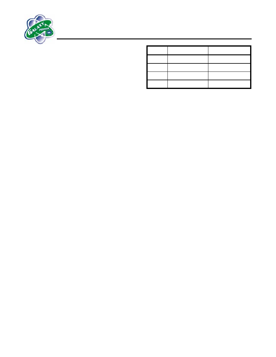
# Cells
+VDC Input
Install jumper
3 11
VDC
J3
4 13
VDC
J4
5 14.5
VDC
J5
6 16
VDC
None
Note: Do not exceed 16 Volts input
Display Functions
The display functions implemented on the MCU
demo board consist of two groups. The first group is
common to all implementations of the MCU
controlled charger and consist of four LEDs that
indicate the status of the charging process. If the
charger is started and no battery is connected to its
output, the "POLL" LED will light to indicate the
charger is looking for a battery to charge. (During a
charge cycle, this LED will flicker as this line is also
used to transmit serial data to the RS232 port).
When a battery is connected (and the thermistor
circuit is enabled) the MCU will read the temperature
of the battery. If it is too hot to charge, the "HOT"
LED will blink and remain blinking at a half second
rate until the battery has cooled enough to accept a
charge. If the battery is too cold to accept a charge,
the "HOT" LED will turn on and remain on until the
battery has warmed up enough to accept a charge.
If the battery temperature is ok, the "CHARGE" LED
will light to indicate that the battery is being charged.
After the charge cycle is complete the "CHARGE"
LED will extinguish and the "MAINT" LED will light to
indicate the main charge cycle is complete., The
battery is ready to use and the MCU is performing a
topping charge function.
The Bargraph display is implemented on the MCU
demo board to show some of the additional
functionality that an MCU based charger could have.
It consists of ten LEDs, three red, four yellow and
three green LEDs arranged in a thermometer style
bargraph and two additional LEDs that indicate what
the bargraph is currently displaying, one labeled
"HEALTH" and one labeled "TEMP". A legend is
printed on the board to remind the end-user of how
they indicate. When a charge cycle is initiated, the
MCU does a self check of the function by
sequentially lighting and extinguishing the LEDs. It
then measures the battery pack temperature and
lights the "TEMP" LED and an appropriate LED on
the bargraph to indicate the relative temperature of
the battery pack with red indicating hot, yellow
indicating normal temperature, and green cold. If a

3
Motorola MCU based Quicksaver Evaluation Board
defective battery pack is installed, the bargraph will
indicate this by lighting all the LEDs in the bargraph
if it detects an open (or missing) battery, then
extinguishing LEDs in pairs starting from the center
then moving out as if a door was opening. It will
repeat this until the problem is resolved. If a battery
pack with shorted cells is detected, the MCU will
light the LEDs on the ends of the bargraph then
proceed to light additional LEDs in pairs until all the
LEDs are lit, as if a door was closing. The "HEALTH"
and "TEMP" LEDs will flash to indicate that the
battery is suspect.
If a good battery pack is installed, the MCU will
proceed to charge this pack, and the bargraph will
display relative voltage on the display with red
indicating a low state of charge and green indicating
a higher state.
The MCU based charger has three modes of
terminating the charge cycle. The normal mode of
termination is for the voltage slope to reach a
predetermined level. After the charge cycle is
complete, the MCU will flash the "HEALTH" LED,
and indicate the termination method. For a voltage
slope termination, the three green LEDs in the
bargraph will be lit. An additional method of charge
termination is for the rise in temperature to cause a
temperature slope termination. If this happens the
"HEALTH" LED will flash and the three red LEDs will
be lit. If the battery pack fails to charge in the allotted
time, the "HEALTH" LED will flash and the four
yellow LEDs will be lit. This could be caused by a
defective battery or inappropriate current levels to be
selected for the pack under charge.
If the battery pack overheats during the charge
cycle, the charge cycle will suspend until the battery
pack cools down and the "TEMP" LED will flash to
indicate that the battery is too hot to accept charge
safely.
BATT
DISPLAY
HEALTH TEMP
VOLTAGE OFF
OFF
TEMP OFF ON
TERM FLASH
OFF
HEALTH ON
OFF
HOT OFF
FLASH
SUSPECT FLASH FLASH
RS232 Port
An optional RS232 port is included on the board to
facilitate detailed analysis of the charging function.
This is an output only port communicating at 19,200
baud that is intended to be connected to the serial
port of a PC. A software package is available that
displays all of the charging parameters in text and
graphic format. This permits the MCU based charger
to be used to critically evaluate the QuickSaver
charging algorithm as well as to provide a method to
evaluate untested battery packs in an application.
This function will permit the unit to replace
expensive battery evaluation test equipment in the
lab at a fraction of the cost and provide more
detailed information than from units currently
available. Please contact Galaxy Power, Inc. for
pricing and detailed information on this software
package.
QuickChek
Health Algorithm
Galaxy Power's new QuickChek battery health
algorithm is implemented on this evaluation board.
This allows the user to quickly determine the health
of any battery connected to the system. During the
charge cycle, the algorithm estimates the charging
time required for charging a new or healthy battery,
then tracks the actual number of charge pulses
required to actually charge the battery. Based on
these measurements, it determines the actual
condition of the battery under charge and indicates
this on the bargraph display. This health
determination is most accurate on a battery that is
nearly discharged, but will provide valid information
on any battery that is connected regardless of state
of charge. This permits the user to determine if the
battery under charge needs to be replaced.
The QuickSaver charging algorithm is very good at
restoring functionality to old or poorly charged
batteries. Therefore the user should be cautioned
that a suspect battery should be charged several
times using the QuickSaver charging algorithm
before it is discarded. The QuickChek algorithm is a
good way to measure the improvements gained by
using the Galaxy Power QuickSaver charging
algorithm. In many cases batteries that are nearly
unusable can be brought back to near perfect
condition by charging them several times using the
QuickSaver charging algorithm.

4
Motorola MCU based Quicksaver Evaluation Board
QuickChek Health Display
Indications
When the battery completes its charge cycle, the
MAINT LED will light to indicate that charge is
complete. At this point, one of the three color groups
will light to indicate the method of charge termination
that QuickSaver utilized to terminate the charge
cycle. The HEALTH LED will flash to indicate that
the termination method is being displayed. If three
green LEDs light, this indicates that the voltage
slope method of termination was used by
QuickSaver to terminate charge. For NiCd batteries,
this will be the usual method of charge termination
as this type of battery is endothermic and actually
cools down unless it is overcharged.
Three red LEDs indicates that the charge was
terminated on temperature slope. For NiMH cells this
method may occur around 50% of the time and is
normal for this cell chemistry. NiMH cells are
exothermic and heat up under normal charging
conditions. There is a race between voltage slope
and temperature slope at the end of the charging
cycle and factors such as initial cell temperature and
initial state of charge have a strong influence on the
termination method utilized. With the QuickSaver
algorithm, the user can be assured that cell
temperature (and internal cell pressure) is safely
controlled.
Four yellow LEDs indicate that QuickSaver
determined that an unusual amount of charging time
was required to charge the cell. This could be
caused by several factors. If the charging current
was set improperly for the cells under charge
(1200mA for a 1600mA cell for example) and the
battery never was fully charged. It is also possible
that the battery has serious problems and is not
properly accepting charge.
This indication will be displayed for approximately 15
seconds, then the HEALTH LED will light steadily
and for an additional 15 seconds, the bargraph will
indicate the health of the battery pack by lighting one
of the bargraph LEDs to indicate the health of the
battery. The display will alternate between displaying
the termination method and battery health on a 15
second interval.
NOTE:
It is absolutely essential for the charging current to
be accurately set for the QuickChek health
algorithm's output to have any validity. Please set up
the charging current carefully. This evaluation board
is only set up for a 1 hour charging rate. The
charging current must be set up for the rated 1 hour
current rating of the battery as specified by the
battery manufacturers data sheet for this to have
any meaning.
Summary
The MCU based evaluation board is intended to
demonstrate the capabilities of the QuickSaver
charging algorithm when implemented in a
microcontroller based charger. Galaxy Power, Inc.
feels that end-users will quickly discover the
flexibility that this approach permits and suggest
many additional functions that could be implemented
with this approach. Although a Motorola
microcontroller was used to implement this design,
virtually any of the microcontrollers that are available
in the marketplace could be used to implement our
patented QuickSaver algorithm. Tradeoffs between
functionality and price can be easily implemented
using this approach. The present unit has
considerably more code space available so that
additional functions could be implemented that you
might desire in a battery charging system. This
system was implemented in assembly language;
however, Galaxy Power, Inc. has also implemented
our algorithm in "C" language and has implemented
this in Windows based systems, Win CE, Pocket PC
and other operating systems. The possibilities for
using the QuicksSaver charging algorithm in
embedded systems are virtually endless, and limited
only by your imagination.
5
Motorola MCU based Quicksaver Evaluation Board
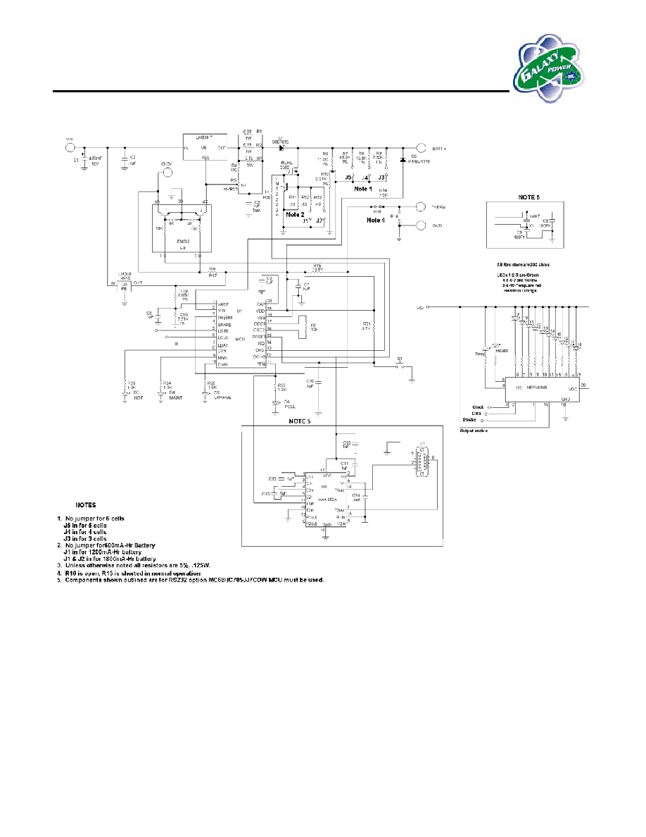
Schematic Diagram
CAUTION!
Do not touch current sense resistors R1, R2, and R3 while unit is operating. They will be very
hot! This is normal, but could cause burns.

6
Motorola MCU based Quicksaver Evaluation Board
Ordering Information
M-QSC1702-EB Standard version
M-QSC1702/RS232-EB Version with RS232 data port
Galaxy Power, Inc.
2500 Eisenhower Avenue
PO Box 890
Valley Forge, PA 19482-0890
Phone: 610-676-0188
FAX: 610-676-0189
http://www.galaxypower.com/
e-mail:
rogers@galaxypower.com
NOTES