ˋ2001 Fairchild Semiconductor Corporation
www.fairchildsemi.com
Rev. 1.0.1
Features
ñ Internally trimmed offset voltage: 10mV
ñ Low input bias current : 50pA
ñ Wide gain bandwidth : 4MHz
ñ High slew rate : 13V/
ç
s
ñ High input impedance : 10
12
Description
The LF351 is JFET input operational amplifier with an inter-
nally compensated input offset voltage. The JFET input
device provides wide bandwidth, low input bias currents and
offset currents.
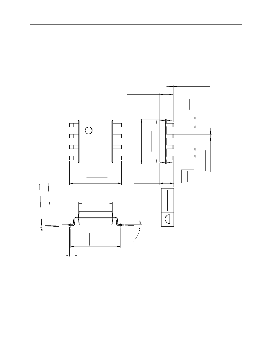
8-DIP
8-SOP
1
1
Internal Block Diagram
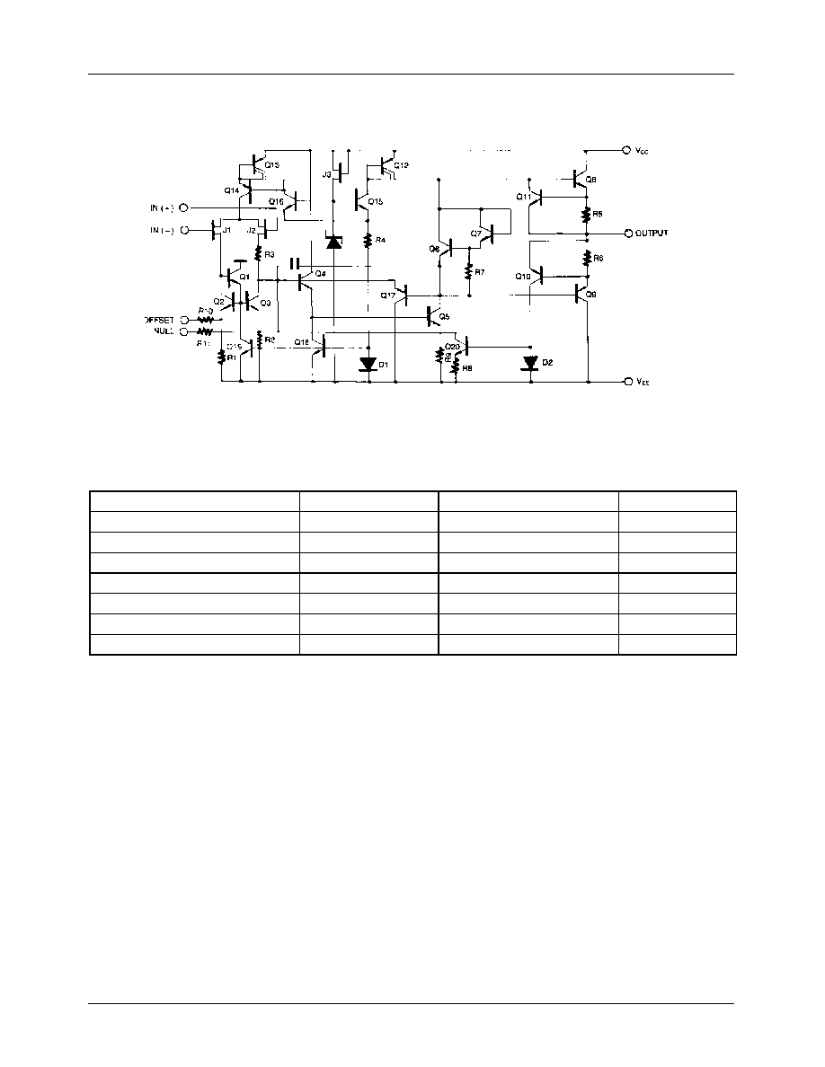
LF351
Single Operational Amplifier (JFET)
LF351
2
Schematic Diagram
Absolute Maximum Ratings
Parameter
Symbol
Value
Unit
Supply Voltage
V
CC
Ý
18
V
Differential Input Voltage
V
I(DIFF)
30
V
Input Voltage Range
V
I
Ý
15
V
Output Short Circuit Duration
-
Continuous
-
Power Dissipation
P
D
500
mW
Operating Temperature
T
OPR
0 ~ +70
¯
C
Storage Temperature Range
T
STG
-65 ~ +150
¯
C

LF351
3
Electrical Characteristics
(V
CC
= +15V, V
EE
= - 15V, T
A
= 25
¯
C. unless otherwise specified)
Note :
1. Guaranteed by design.
Parameter
Symbol
Conditions
Min.
Typ.
Max.
Unit
Input Offset Voltage
V
IO
R
S
= 10k
-
5.0
10
mV
0
¯
C
T
A
70
¯
C
-
-
13
Input Offset Voltage Drift (Note1)
V
IO
/
T
R
S
= 10k
0
¯
C
T
A
70
¯
C
-
10
-
ç
V/
¯
C
Input Offset Current
I
IO
-
25
100
pA
0
¯
C
T
A
70
¯
C
-
-
4
nA
Input Bias Current
I
BAIS
-
50
200
pA
0
¯
C
T
A
70
¯
C
-
-
8
nA
Input Resistance (Note1)
R
I
-
-
10
12
-
Large Signal Voltage Gain
G
V
V
O(P-P)
=
Ý
10V
25
100
-
V/mV
R
L
=2k
0
¯
C
T
A
70
¯
C
15
-
-
Output Voltage Swing
V
O(P-P)
R
L
= 10k
Ý
12
Ý
13.5
-
V
Input Voltage Range
V
I(R)
-
Ý
11
+15
-12
-
V
Common Mode Rejection Ratio
C
MRR
R
S
10k
70
100
-
dB
Power Supply Rejection Ratio
P
SRR
R
S
10k
70
100
-
dB
Power Supply Current
I
CC
-
-
2.3
3.4
mA
Slew Rate (Note1)
S
R
G
V
= 1
-
13
-
V/
ç
s
Gain-Bandwidth Product (Note1)
GBW
-
-
4
-
MHz