www.fairchildsemi.com
REV. 1.0.5 1/29/03
Features
· Fixed 2.500V, 3.300V and 5.00V
· Tolerances to ±0.1% (25
°
C)
· Low output noise
· Low temperature coefficient to 100ppm/°C
· Small package
· Extended operating current range
· Extended temperature range
Applications
· Portable equipment
· Disk drives
· Instrumentation
· Audio equipment
· Data acquisition systems
Description
The FAN4040 series of precision shunt references are ideal
for space- and cost-sensitive applications. They are available
in three output voltages (2.500V, 3.300V and 5.00V) and
with four output voltage tolerances (0.1%, 0.2%, 0.5% and
1%). They also have excellent temperature coefficients, to
100ppm/
°
C for the tighter tolerance grades. The FAN4040
series has an extended operating current range, sinking as
much as 25mA.
The FAN4040 series is available in SOT-23 package.
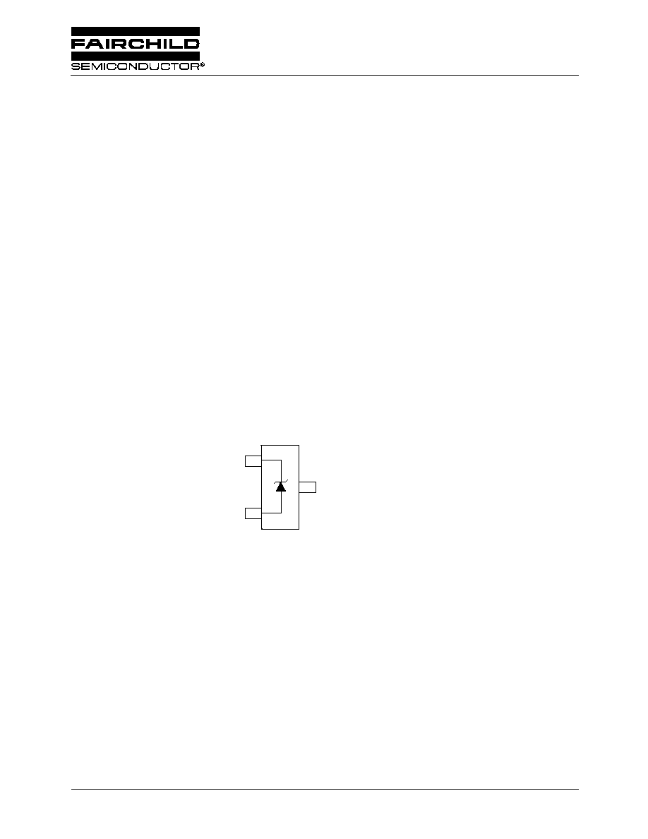
Connection Diagrams
1
2
+
3*
*This pin must be left floating
or connected to pin 2.
SOT-23
Top View
FAN4040
Precision Micropower Shunt Voltage Reference
FAN4040
PRODUCT SPECIFICATION
2
REV. 1.0.5 1/29/03
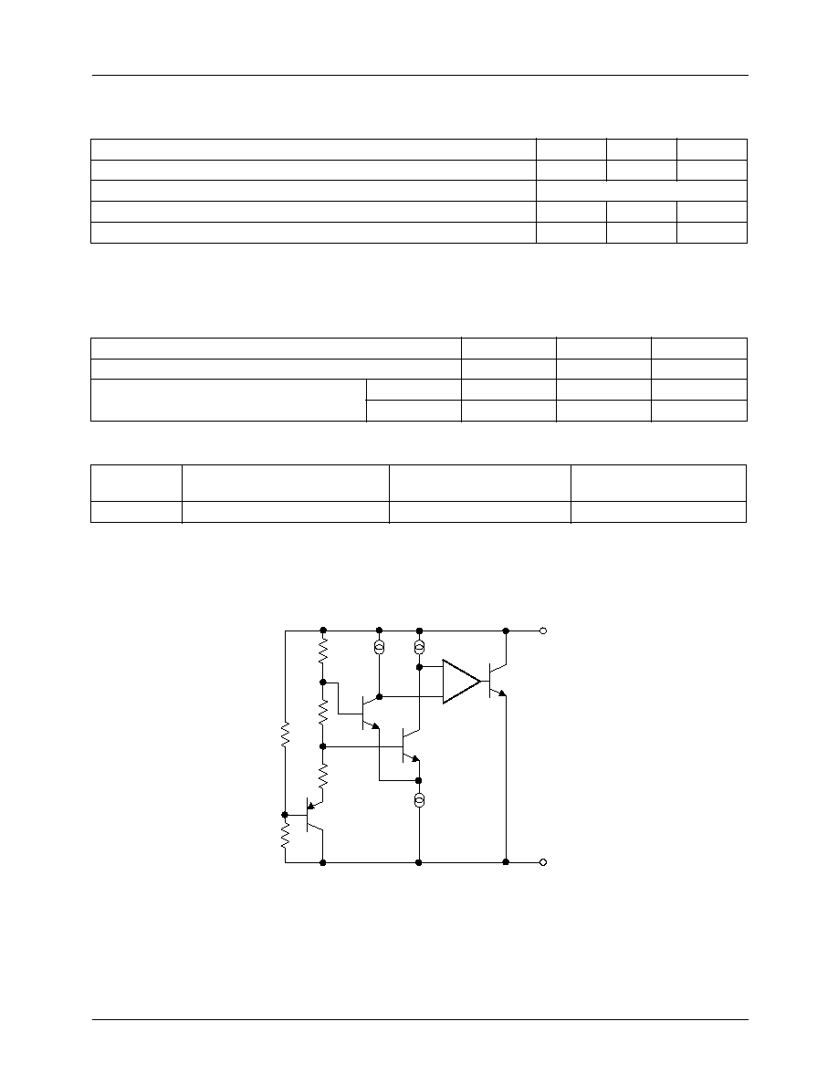
Absolute Maximum Ratings
1
Ratings are over full operating free-air temperature range unless otherwise noted.
Notes:
1. Functional operation under these conditions is not implied. Permanent damage may occur if the device is subjected to
conditions outside these ratings.
Recommended Operating Conditions
Dissipation Rating Table
Note:
1. It is recommended to connect pin 3 to pin 2 to ensure optimal thermal performance.
Equivalent Schematic
Parameter
Min.
Max.
Unit
Continuous cathode current, IK
-30
30
mA
Power dissipation
See Dissipation Rating Table
Storage Temperature Range
-65
150
°C
Lead Temperature (Soldering, 10 sec.)
300
°C
Parameter
Min.
Max.
Unit
Continuous cathode current, IK
0.025
25
mA
Operating temperature range in free air, TA
I Grade
-40
85
°C
E Grade
-40
125
°C
Package
Power Rating
TA
25
°
C
Derating Factor
TA
25
°
C
Power Rating
TA = 70
°
C
SOT23
1
306mW
3.0mW/°C
168mW
+
_
+
_

PRODUCT SPECIFICATION
FAN4040
REV. 1.0.5 1/29/03
3
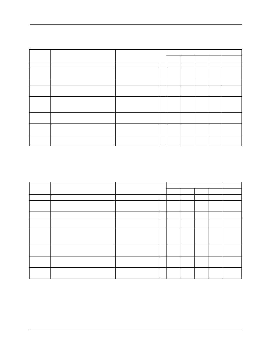
Guaranteed Electrical Characteristics, FAN4040-2.5, Industrial Temperature Range
(T
A
= 25°C unless otherwise specified, in free air)
The
·
denotes specifications which apply over the full operating temperature range.
*Typical.
Guaranteed Electrical Characteristics, FAN4040-3.3, Industrial Temperature Range
(T
A
= 25°C unless otherwise specified, in free air)
The
·
denotes specifications which apply over the full operating temperature range.
*Typical.
Symbol
Parameter
Conditions
Limits
Units
A
B
C
D
VR
Reverse Breakdown Voltage
IK = 100µA
2.500 2.500 2.500 2.500
V*
TCVR
Reverse Breakdown Voltage
Tolerance
IK = 100µA
·
±2.5
±19
±5.0
±21
±12
±29
±25
±49
mV
mV
IRMIN
Minimum Operating Current
·
65
65
65
70
µA
VR/
T
Reverse Breakdown Voltage
Temperature Coefficient
IK = 1mA
·
±100
±100
±100
±150
ppm/
°
C
V
R
(
IK) Reverse Breakdown Voltage
Change with Operating Current
I
RMIN
I
K
1mA
1mA
I
K
15mA
1mA
I
K
25mA
·
·
1.2
8.0
10
1.2
8.0
10
1.2
8.0
10
1.5
10.0
12
mV
mV
mV*
ZKA
Reverse Dynamic Impedance
IK=1mA, f=120Hz,
IAC=0.1IK
1.0
1.0
1.0
1.3
*
eN
Wideband Noise
IK=100µA,
10Hz
f
10kHz
35
35
35
35
µVRMS*
VR
Reverse Breakdown Voltage
Long-term Stability
t=1000hrs, T=25°C,
IK=100µA
120
120
120
120
ppm*
Symbol
Parameter
Conditions
Limits
Units
A
B
C
D
VR
Reverse Breakdown Voltage
IK = 100µA
3.300 3.300 3.300 3.300
V*
TCVR
Reverse Breakdown Voltage
Tolerance
IK = 100µA
·
±3.3
±25
±6.6
±28
±17
±38
±33
±65
mV
mV
IRMIN
Minimum Operating Current
·
70
70
70
75
µA
VR/
T
Reverse Breakdown Voltage
Temperature Coefficient
IK = 1mA
·
±100
±100
±100
±150
ppm/
°
C
V
R
(
IK) Reverse Breakdown Voltage
Change with Operating Current
I
RMIN
I
K
1mA
1mA
I
K
15mA
1mA
I
K
25mA
·
·
1.2
10
12
1.2
10
12
1.2
10
12
1.5
13
15
mV
mV
mV*
ZKA
Reverse Dynamic Impedance
IK=1mA, f=120Hz,
IAC=0.1IK
1.0
1.0
1.0
1.3
*
eN
Wideband Noise
IK=100µA,
10Hz
f
10kHz
70
70
70
70
µVRMS*
VR
Reverse Breakdown Voltage
Long-term Stability
t=1000hrs, T=25°C,
IK=100µA
120
120
120
120
ppm*

FAN4040
PRODUCT SPECIFICATION
4
REV. 1.0.5 1/29/03
Guaranteed Electrical Characteristics, FAN4040-5.0, Industrial Temperature Range
(T
A
= 25°C unless otherwise specified, in free air)
The
·
denotes specifications which apply over the full operating temperature range.
*Typical.
Guaranteed Electrical Characteristics, FAN4040-2.5, Extended Temperature Range
(T
A
= 25°C unless otherwise specified, in free air)
The
·
denotes specifications which apply over the full operating temperature range.
*Typical.
Symbol
Parameter
Conditions
Limits
Units
A
B
C
D
VR
Reverse Breakdown Voltage
IK = 100µA
5.00
5.00
5.00
5.00
V*
TCVR
Reverse Breakdown Voltage
Tolerance
IK = 100µA
·
±5
±40
±10
±45
±24
±60
±50
±100
mV
mV
IRMIN
Minimum Operating Current
·
65
65
65
70
µA
VR/
T
Reverse Breakdown Voltage
Temperature Coefficient
IK = 1mA
·
±100
±100
±100
±150
ppm/
°
C
V
R
(
IK) Reverse Breakdown Voltage
Change with Operating Current
I
RMIN
I
K
1mA
1mA
I
K
15mA
1mA
I
K
25mA
·
·
1.2
8.0
10
1.2
8.0
10
1.2
8.0
10
1.5
10.0
12
mV
mV
mV*
ZKA
Reverse Dynamic Impedance
IK=1mA, f=120Hz,
IAC=0.1IK
1.0
1.0
1.0
1.3
*
eN
Wideband Noise
IK=100µA,
10Hz
f 10kHz
70
70
70
70
µVRMS*
VR
Reverse Breakdown Voltage
Long-term Stability
t=1000hrs, T=25°C,
IK=100µA
120
120
120
120
ppm*
Symbol
Parameter
Conditions
Limits
Units
A
B
C
D
VR
Reverse Breakdown Voltage
IK = 100µA
2.500 2.500 2.500 2.500
V*
TCVR
Reverse Breakdown Voltage
Tolerance
IK = 100µA
·
±2.5
±25
±5.0
±30
±12
±35
±25
±49
mV
mV
IRMIN
Minimum Operating Current
·
65
65
65
70
µA
VR/T
Reverse Breakdown Voltage
Temperature Coefficient
IK = 1mA
· ±100 ±100 ±100 ±150 ppm/°C
V
R
(
IK) Reverse Breakdown Voltage
Change with Operating Current
I
RMIN
I
K
1mA
1mA
I
K
15mA
1mA
I
K
25mA
·
·
1.5
10.0
10
1.5
10.0
10
1.5
10.0
10
1.5
10.0
12
mV
mV
mV*
ZKA
Reverse Dynamic Impedance
IK=1mA, f=120Hz,
IAC=0.1IK
1.0
1.0
1.0
1.3
*
eN
Wideband Noise
IK=100µA,
10Hz
f 10kHz
70
70
70
70
µVRMS*
VR
Reverse Breakdown Voltage
Long-term Stability
t=1000hrs, T=25°C,
IK=100µA
120
120
120
120
ppm*
PRODUCT SPECIFICATION
FAN4040
REV. 1.0.5 1/29/03
5
Guaranteed Electrical Characteristics, FAN4040-3.3, Extended Temperature Range
(T
A
= 25°C unless otherwise specified, in free air)
The
· denotes specifications which apply over the full operating temperature range.
*Typical.
Guaranteed Electrical Characteristics, FAN4040-5.0, Extended Temperature Range
(T
A
= 25°C unless otherwise specified, in free air)
The
· denotes specifications which apply over the full operating temperature range.
*Typical.
Symbol
Parameter
Conditions
Limits
Units
A
B
C
D
VR
Reverse Breakdown Voltage
IK = 100µA
3.300 3.300 3.300 3.300
V*
TCVR
Reverse Breakdown Voltage
Tolerance
IK = 100µA
·
±3.3
±30
±6.6
±35
±17
±42
±33
±65
mV
mV
IRMIN
Minimum Operating Current
·
70
70
70
75
µA
VR/T
Reverse Breakdown Voltage
Temperature Coefficient
IK = 1mA
· ±100 ±100 ±100 ±150 ppm/°C
V
R
(
IK) Reverse Breakdown Voltage
Change with Operating Current
I
RMIN
I
K
1mA
1mA
I
K
15mA
1mA
I
K
25mA
·
·
1.5
10
12
1.5
10
12
1.5
10
12
1.5
13
15
mV
mV
mV*
ZKA
Reverse Dynamic Impedance
IK=1mA, f=120Hz,
IAC=0.1IK
1.0
1.0
1.0
1.3
*
eN
Wideband Noise
IK=100µA,
10Hz
f 10kHz
70
70
70
70
µVRMS*
VR
Reverse Breakdown Voltage
Long-term Stability
t=1000hrs, T=25°C,
IK=100µA
120
120
120
120
ppm*
Symbol
Parameter
Conditions
Limits
Units
A
B
C
D
VR
Reverse Breakdown Voltage
IK = 100µA
5.00
5.00
5.00
5.00
V*
TCVR
Reverse Breakdown Voltage
Tolerance
IK = 100µA
·
±5
±50
±10
±60
±24
±70
±50
±100
mV
mV
IRMIN
Minimum Operating Current
·
100
100
100
100
µA
VR/T
Reverse Breakdown Voltage
Temperature Coefficient
IK = 1mA
· ±100 ±100 ±100 ±150 ppm/°C
V
R
(
IK) Reverse Breakdown Voltage
Change with Operating Current
I
RMIN
I
K
1mA
1mA
I
K
15mA
1mA
I
K
25mA
·
·
1.5
10
10
1.5
10
10
1.5
10
10
1.5
15
12
mV
mV
mV*
ZKA
Reverse Dynamic Impedance
IK=1mA, f=120Hz,
IAC=0.1IK
1.0
1.0
1.0
1.3
*
eN
Wideband Noise
IK=100µA,
10Hz
f 10kHz
70
70
70
70
µVRMS*
VR
Reverse Breakdown Voltage
Long-term Stability
t=1000hrs, T=25°C,
IK=100µA
120
120
120
120
ppm*