®
MR
850 GP
50
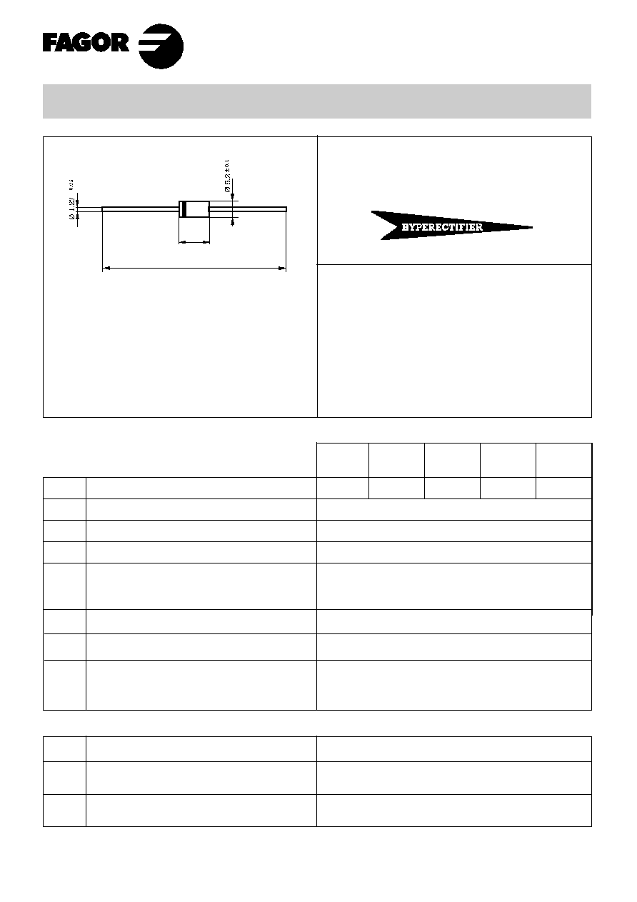
MR850GP......MR856GP
3 Amp. Glass Passivated Fast Recovery Rectifier
Mounting instructions
1. Min. distance from body to soldering point,
4 mm.
2. Max. solder temperature, 350 °C.
3. Max. soldering time, 3.5 sec.
4. Do not bend lead at a point closer than
3 mm. to the body.
Dimensions in mm.
DO-201 AD
(Plastic)
Maximum Ratings, according to IEC publication No. 134
Peak recurrent and non recurrent reverse voltage (V)
Forward current at Tamb = 90 °C
Recurrent peak forward current (A)
10 ms. peak forward surge current
V
RRM
I
F(AV)
I
FRM
I
FSM
3.0 A
15 A
100 A
T
j
T
stg
Operating temperature range
Storage temperature range
65 to + 175 °C
65 to + 175 °C
Electrical Characteristics at Tamb = 25 °C
V
F
Max. forward voltage drop at I
F
= 3 A
I
R
5 µ A
100 µ A
1.25 V
Max. reverse current at V
RRM
t
rr
Max. reverse recovery
time from
R
thj-a
Thermal resistance (I = 10 mm.)
30 °C/W
15 °C/W
at 25
o
C
at 125
o
C
Voltage
50 to 600 V.
Current
3.0 A. at 90 °C.
· Glass passivated junction
· High current capability
· The plastic material carries
U/L recognition 94 V-0
· Terminals: Axial Leads
· Polarity: Color band denotes cathode
Max.
Typ.
150 ns
MR
851 GP
100
MR
852 GP
200
MR
854 GP
400
MR
856 GP
600
I
F
I
R
I
RR
= 0.5 A
= 1 A
= 0.25 A
E
RSM
Maximum non repetitive peak
reverse avalanche energy.
I
R
= 1A ; T
J
= 25 şC
20 mJ
9.1
± 0.3
62.5
± 0.5

10 mm. - 10 mm.
T
j
= 25 °C
V
F '
instantaneous forward voltage (V)
Rating And Characteristic Curves
0.6
0.8
1.2
1.4
1.6
0
25
50
75
100 125
175
150
Tamb, ambient temperature (şC)
100
1
10
100
MAXIMUM NON REPETITIVE
PEAK FORWARD SURGE CURRENT
TYPICAL JUNCTION CAPACITANCE
V
R
reverse voltage (V)
1
2
4
6
10
20
40
100
Number of cycles at 50 Hz.
TYPICAL FORWARD CHARACTERISTIC
FORWARD CURRENT DERATING CURVE
100
10
1
0.1
1
MR850GP
4
3
2
1
100
75
50
25
0
50
5
5
50
10
T
j
= 25şC
f = 1 MHz
5
T
j
= 25şC