
EXAR Corporation, 48720 Kato Road, Fremont, CA 94538
·
(510) 668-7000
·
FAX (510) 668-7017
XRD9855/L55
CCD Image Digitizers with
CDS, PGA and 10-Bit A/D
December 1998-2
FEATURES
l
10-Bit Resolution ADC
l
Up to 25MHz Sampling Rate
l
Correlated Double Sampling (CDS)
l
Programmable Gain from 6dB to 38dB (PGA)
l
Digital Offset-Calibration
l
CCD Black Level Offset Compensation
l
CDS Clocks Sample Rising Edge or Falling Edge
l
Single 5V or 3V Power Supply
l
Low Power for Battery Applications:
XRD9855: 250mW @ V
DD
= 5.0V
XRD98L55: 120mW @ V
DD
= 3.0V
l
50
µ
A-Typ Current in Stand By Mode
l
3-State Digital Outputs
l
ESD Protection to Over 2000V
APPLICATIONS
l
Digital Video Camcorders
l
Digital Still Cameras
l
PC Video Teleconferencing
l
Digital Copiers
l
Infrared Image Digitizers
l
CCD/CIS Imager Interface
GENERAL DESCRIPTION
The XRD9855/XRD98L55 are complete CCD Image
Digitizers for digital cameras. The products include a
high bandwidth differential Correlated Double Sampler
(CDS), 8-bit digitally Programmable Gain Amplifier
(PGA), 10-bit Analog-to-Digital Converter (ADC) and
digital black level auto-calibration circuitry.
The Correlated Double Sampler (CDS) subtracts the
CCD output signal black level from the video level.
Common mode signal noise and power supply noise are
rejected by the differential CDS input stage. CDS inputs
are designed to be used either differential or single-
ended.
The auto calibration circuit compensates for any inter-
nal offset of the XRD9855/XRD98L55 as well as black
level offset from the CCD.
The PGA is digitally controlled with 8-bit resolution on
a linear dB scale, resulting in a gain range of 6dB to
38dB with 0.125dB per LSB of the gain code.
The PGA and black level auto-calibration are controlled
through a simple 3-wire serial interface. The timing
circuitry is designed to enable users to select a wide
variety of available CCD and image sensors for their
applications.
The XRD9855/XRD98L55 has direct access to the
PGA output and ADC input through the pin TESTVIN.
The XRD9855/XRD98L55 are packaged in 48-lead
surface mount TQFP to reduce space and weight, and
suitable for hand-held and portable applications.
ORDERING INFORMATION
Operating
Part No.
Package
Temperature Range
Power Supply
XRD9855AIV
48 Lead TQFP (7 x 7 x 1.0 mm)
-40
°
C to 85
°
C
5.0V
XRD98L55AIV
48 Lead TQFP (7 x 7 x 1.0 mm)
-40
°
C to 85
°
C
3.0V
Preliminary

XRD9855/L55
2
Rev. 1.00
Preliminary
Figure 1. XRD9855/XRD98L55 Simplified Block Diagram
ADC
CDS
PGA
DB[9:0]
In_Pos
In_Neg
SHP
SHD
SCLK
CLAMP
V
RTO
V
DD
V
RBO
GND
V
RT
V
RB
RSTCCD
OE
RESET
OVER
UNDER
Reg
Offset
Calibration
Serial Port
Registers
Timing
Generator
SDI
LOAD
STBY1
STBY2
DGND
DV
DD
SYNC
V
DD
GND
CLK_POL
EnableCal
TESTVIN

XRD9855/L55
3
Rev. 1.00
Preliminary
PIN CONFIGURATION
48 Lead TQFP (7 x 7 x 1.0 mm)
PIN DESCRIPTION 48 pin TQFP
Pin #
Symbol
Description
1
NC
No Connect.
2
NC
No Connect.
3
DB2
ADC Output. DB0 is the LSB, DB9 is the MSB.
4
DB3
ADC Output.
5
DB4
ADC Output.
6
DGND
Digital Output Ground.
7
DV
DD
Digital Output Power Supply. Must be less than or equal to V
DD
.
8
DB5
ADC Output.
9
DB6
ADC Output.
10
DB7
ADC Output.
11
NC
No Connect.
12
NC
No Connect.
13
DB8
ADC Output.
14
DB9
ADC Output. MSB
15
OVER
Over Range Output Bit. OVER goes high to indicate the ADC input voltage is
greater than V
RT
.
36
25
24
13
1
12
37
48
CLAMP
SHD
SHP
RSTCCD
GND
CLK_POL
V
DD
SYNC
UNDER
DB0
DB1
NC
DB8
DB9
OVER
OE
V
DD
EnableCal
GND
Test
STBY1
STBY2
RESET
SCLK
DB2
DB3
DB4
DGND
DB5
DB6
DB7
DV
DD
NC
NC
NC
NC
LOAD
SDI
V
RT
V
RTO
V
RB
In_Neg
In_Pos
GND
V
RBO
DD
V
NC
NC

XRD9855/L55
4
Rev. 1.00
Preliminary
PIN DESCRIPTION 48 pin TQFP (CONT'D)
Pin #
Symbol
Description
16
OE
Digital Output Enable (Three-State Control). Pull OE low to enable output
drivers. Pull OE high to put output drivers in high impedance state.
17
V
DD
Analog Power Supply.
18
EnableCal
Calibration Enable. Automatic offset calibration control.
19
GND
Analog Ground.
20
TESTVIN
ADC Test Input & PGA Test Output.
21
STBY1
Standby Control 1. Pull low to put chip in power down mode.
22
STBY2
Standby Control 2. Short to STBY1 pin if not using TESTVIN pin.
23
RESET
Chip Reset. Pull high to reset all internal registers.
24
SCLK
Shift Clock. Shift register latches SDI data on rising edges of SCLK.
25
NC
No Connect.
26
LOAD
Data Load. Rising edge loads data from shift register to internal register. Load
must be low to enable shift register.
27
SDI
Serial Data Input.
28
V
RT
Top ADC Reference. Voltage at V
RT
sets full-scale of ADC.
29
V
RTO
Internal Bias for V
RT
. Short V
RT
to V
RTO
to use internal reference voltage.
30
V
DD
Analog Power Supply.
31
In_Neg
CDS Inverting Input. Connect via capacitor to CCD video output.
32
In_Pos
CDS Non-inverting Input. Connect via capacitor to CCD supply.
33
GND
Analog Ground.
34
V
RBO
Internal Bias for V
RB.
Short V
RB
to V
RB0
to use internal reference voltage.
35
V
RB
Bottom ADC Reference. Voltage at V
RB
sets zero scale of the ADC.
36
NC
No Connect.
37
CLAMP
CDS DC Restore Clamp. Clamps In_Pos & In_Neg to internal bias voltage.
38
SHD
CDS Clock. Controls sampling of the pixel video level.
39
SHP
CDS Clock. Controls sampling of the pixel black level.
40
RSTCCD
CCD Reset Pulse Disconnect. Used to decouple CDS during the reset pulse.
41
GND
Analog Ground.
42
CLK_POL
Clock Polarity. Controls the polarity of SHP, SHD & CLAMP.
43
V
DD
Analog Power Supply.
44
SYNC
Digital output for Exar test purposes only. No connect.
45
UNDER
Under Range Output Bit. UNDER goes high to indicate the ADC input voltage
is less than V
RB
.
46
DBO
ADC Output. LSB
47
DB1
ADC Output.
48
NC
No Connect.
XRD9855/L55
5
Rev. 1.00
Preliminary
DC ELECTRICAL CHARACTERISTICS XRD9855
Unless otherwise specified: DV
DD
= V
DD
= 5.0V, Pixel Rate = 18MSPS, V
RT
= 3.8V, V
RB
= 0.5V
Symbol
Parameter
Min.
Typ.
Max.
Unit
Conditions
CDS Performance
CDSV
IN
Input Range
200
800
mV
PP
Pixel (Black Level - Video Level)
BW
Small Signal Bandwidth (-3dB)
60
MHz
SR
Slew Rate
40
V/µs
400mV Step Input.
FT
Feedthrough (Hold Mode)
-60
dB
PGA Parameters
AV
MIN
Minimum Gain
6
dB
AV
MAX
Maximum Gain
38
dB
PGA n
Resolution
8
bits
Transfer function is linear steps in dB
(1LSB = 0.125dB).
GE
Gain Error
5
% FS
At maximum or minimum gain
setting.
ADC Parameters (Measured Through TESTVIN)
ADC n
Resolution
10
bits
f
s
Max Sample Rate
25
MSPS
DNL
Differential Non-Linearity
+0.75
LSB
Up to 18MHz sample rate.
DNL25
Differential Non-Linearity
+0.9
LSB
Up to 25MHz sample rate.
EZS
Zero Scale Error
-5
5
mV
Measured relative to V
RB
.
EFS
Full Scale Error
4
% FS
V
IN
DC Input Range
GND
V
DD
V
V
IN
of the ADC can swing from GND
to V
DD
. Input range is limited by
the output swing of the PGA.
V
RT
Top Reference Voltage
1.3
3.8
V
DD
V
V
RT
>V
RB
V
RB
Bottom Reference Voltage
0.3
0.5
V
DD
-1
V
V
RT
>V
RB
V
REF
Differential Reference Voltage
1.0
3.3
V
DD
V
R
L
Ladder Resistance
500
Ohms
V
RB
Self Bias V
RB
0.5
V
V
RB
connected to V
RBO.
V
RT
Self Bias V
RT
3.8
V
V
RT
connected to V
RTO.
(
V
RB
= V
DD
10
)
(
V
RT
= V
DD
1.30
)

XRD9855/L55
6
Rev. 1.00
Preliminary
DC ELECTRICAL CHARACTERISTICS XRD9855 (CONT'D)
Unless otherwise specified: DV
DD
= V
DD
= 5.0V, Pixel Rate = 18MSPS, V
RT
= 3.8V, V
RB
= 0.5V
Symbol
Parameter
Min.
Typ.
Max.
Unit
Conditions
System Specifications
DNL
SMIN
DNL @ Minimum Gain
0.75
LSB
DNL
SMAX
DNL @ Maximum Gain
0.75
LSB
INL
SMIN
INL @ Minimum Gain
2
LSB
INL error is dominated by CDS/PGA
linearity.
INL
SMAX
INL @ Maximum Gain
2
LSB
INL error is dominated by CDS/PGA
linearity.
V
OS MINAV
Offset (Input Referred) @
5
mV
Offset is defined as the input pixel
Minimum Gain
value-0.5 LSB required to cause the
ADC output to switch from "Zero
scale" to "Zero scale + 1LSB".
Offset is measured after calibration.
V
OS MAXAV
Offset (Input Referred) @
1
mV
Zero scale is the code in the offset
Maximum Gain
register.
Offset depends on PGA gain code.
en
MAXAV
Input Referred Noise @
0.2
mV
rms
Noise depends upon gain setting of
Maximum Gain
the PGA.
en
MINAV
Input Referred Noise @
3.5
mV
rms
Noise depends upon gain setting of
Minimum Gain
the PGA.
Digital Inputs
V
IH
Digital Input High Voltage
2.0
V
V
IL
Digital Input Low Voltage
0.7
V
I
L
DC Leakage Current
5
µ
A
Input Between GND and V
DD.
C
IN
Input Capacitance
5
pF
Digital Outputs
V
OH
Digital Output High Voltage
DV
DD
-0.5
V
While sourcing 2mA.
V
OL
Digital Output Low Voltage
0.5
V
While sinking 2mA.
I
OZ
High-Z Leakage
-10
10
µ
A
OE=1 or STBY1= STBY2 = 0.
Output between GND & DV
DD.

XRD9855/L55
7
Rev. 1.00
Preliminary
DC ELECTRICAL CHARACTERISTICS XRD9855
Unless otherwise specified: DV
DD
= V
DD
= 5.0V, Pixel Rate = 18MSPS, V
RT
= 3.8V, V
RB
= 0.5V
Symbol
Parameter
Min.
Typ.
Max.
Unit
Conditions
Digital I/O Timing
T
DL
Data Valid Delay
20
25
ns
T
PW1
Pulse Width of SHD
10
ns
T
PW2
Pulse Width of SHD
10
ns
T
PIX
Pixel Period
40
56
ns
T
BK
Sample Black Aperture Delay
4
6
ns
V
DD
= 4.5V to 5.5V,
Temperature -40°C to 85°C range
T
VD
Sample Video Aperture Delay
3
5
ns
V
DD
= 4.5V to 5.5V,
Temperature -40°C to 85°C range
T
RST
RSTCCD Switch Delay
0
4
ns
V
DD
= 4.5V to 5.5V,
Temperature -40°C to 85°C range
T
SC
Shift Clock Period
50
100
ns
T
SET
Shift Register Setup Time
10
ns
Latency
Pipeline Delay
4
cycles
Power Supplies
V
DD
Analog Supply Voltage
4.5
5.0
5.5
V
DV
DD
Digital Output Supply Voltage
2.7
5.0
5.5
V
DV
DD
< V
DD
Always
I
DD
Supply Current
50
75
mA
DV
DD
=
V
DD
= 5.0V
I
DD25
Supply Current @ 25MHz
55
85
mA
F
S
= 25MHz
I
DDPD
Power Down Supply Current
50
100
µ
A
STBY1 = 0 and STBY2 = 0

XRD9855/L55
8
Rev. 1.00
Preliminary
DC ELECTRICAL CHARACTERISTICS XRD98L55
Unless otherwise specified: DV
DD
= V
DD
= 2.7V, Pixel Rate = 18MSPS, V
RT
= 2.07V, V
RB
= 0.27V
Symbol
Parameter
Min.
Typ.
Max.
Unit
Conditions
CDS Performance
CDSV
IN
Input Range
200
800
mV
PP
Pixel (Black Level - Video Level)
BW
Small Signal Bandwidth (-3dB)
60
MHz
SR
Slew Rate
40
V/µs
400mV Step Input.
FT
Feed-through (Hold Mode)
-60
dB
PGA Parameters
AV
MIN
Minimum Gain
6
dB
AV
MAX
Maximum Gain
38
dB
PGA n
Resolution
8
bits
Transfer function is linear steps in dB
(1LSB = 0.125dB).
GE
Gain Error
5
% FS
At maximum or minimum gain
setting.
ADC Parameters (Measured Through TESTVIN)
ADC n
Resolution
10
bits
f
s
Max Sample Rate
25
MSPS
DNL
Differential Non-Linearity
+0.75
LSB
Up to 18MHz sample rate.
DNL25
Differential Non-Linearity
+0.9
LSB
Up to 25MHz sample rate.
EZS
Zero Scale Error
-5
5
mV
Measured relative to V
RB
.
EFS
Full Scale Error
4
% FS
V
IN
DC Input Range
GND
V
DD
V
V
IN
of the ADC can swing from GND to
V
DD
. Input range is limited by
the output swing of the PGA.
V
RT
Top Reference Voltage
1.2
2.07
V
DD
V
V
RT
>V
RB
V
RB
Bottom Reference Voltage
0.2
0.27 V
DD
-1
V
V
RT
>V
RB
V
REF
Differential Reference Voltage
1.0
1.8
V
DD
V
R
L
Ladder Resistance
500
Ohms
V
RB
Self Bias V
RB
0.27
V
V
RB
connected to V
RBO.
V
RT
Self Bias V
RT
2.07
V
V
RT
connected to V
RTO.
(
V
RB
= V
DD
10
)
(
V
RT
= V
DD
1.30
)

XRD9855/L55
9
Rev. 1.00
Preliminary
DC ELECTRICAL CHARACTERISTICS XRD98L55 (CONT'D)
Unless otherwise specified: DV
DD
= V
DD
= 2.7V, Pixel Rate = 18MSPS, V
RT
= 2.7V, V
RB
= 0.27V
Symbol
Parameter
Min.
Typ.
Max.
Unit
Conditions
System Specifications
DNL
SMIN
DNL @ Minimum Gain
0.75
LSB
DNL
SMAX
DNL @ Maximum Gain
0.75
LSB
INL
SMIN
INL @ Minimum Gain
2
LSB
INL error is dominated by CDS/PGA
linearity.
INL
SMAX
INL @ Maximum Gain
2
LSB
INL error is dominated by CDS/PGA
linearity.
V
OS MINAV
Offset (Input Referred) @
5
mV
Offset is defined as the input pixel
Minimum Gain
value -0.5 LSB required to cause the
ADC output to switch from "Zero
scale" to "Zero scale + 1LSB".
Offset is measured after
calibration.
V
OS MAXAV
Offset (Input Referred) @
1
mV
Zero scale is the code in the offset
Maximum Gain
register.
Offset depends on PGA gain code.
en
MAXAV
Input Referred Noise @
0.2
mV
rms
Noise depends upon gain setting of
Maximum Gain
the PGA.
en
MINAV
Input Referred Noise @
3.5
mV
rms
Noise depends upon gain setting of
Minimum Gain
the PGA.
Digital Inputs
V
IH
Digital Input High Voltage
1.5
V
V
IL
Digital Input Low Voltage
0.7
V
I
L
DC Leakage Current
5
µ
A
Input Between GND and V
DD.
C
IN
Input Capacitance
5
pF
Digital Outputs
V
OH
Digital Output High Voltage
DV
DD
-0.5
V
While sourcing 2mA.
V
OL
Digital Output Low Voltage
0.5
V
While sinking 2mA.
I
OZ
HighZ Leakage
-10
10
µ
A
OE=1 or STBY1= STBY2 = 0.
Output between GND & DV
DD.

XRD9855/L55
10
Rev. 1.00
Preliminary
ABSOLUTE MAXIMUM RATINGS (T
A
= +25
°
C unless otherwise noted)
1, 2, 3
V
DD
to GND
+7.0V
V
RT
& V
RB
V
DD
+0.5 to GND -0.5V
V
IN
V
DD
+0.5 to GND -0.5V
All Inputs
V
DD
+0.5 to GND -0.5V
All Outputs
V
DD
+0.5 to GND -0.5V
Storage Temperature
-65
°
C to 150
°
C
Lead Temperature (Soldering 10 seconds)
300
°
C
Maximum Junction Temperature
150
°
C
Package Power Dissipation Ratings (T
A
= +70
°
C)
TQFP
q
JA
= 54
°
C/W
ESD
2000V
Notes:
1
Stresses above those listed as "Absolute Maximum Ratings" may cause permanent damage to the device. This is
a stress rating only and functional operation at or above this specification is not implied. Exposure to maximum
rating conditions for extended periods may affect device reliability.
2
Any input pin which can see a value outside the absolute maximum ratings should be protected by Schottky diode
clamps (HP50822835) from input pin to the supplies. All inputs have protection diodes which will protect the
device from short transients outside the supplies of less than 100mA for less than 100µs.
3
V
DD
refers to AV
DD
and DV
DD
. GND refers to AGND and DGND.
DC ELECTRICAL CHARACTERISTICS XRD98L55 (CONT'D)
Unless otherwise specified: DV
DD
= V
DD
= 2.7V, Pixel Rate = 18MSPS, V
RT
= 2.07V, V
RB
= 0.27V
Symbol
Parameter
Min.
Typ.
Max.
Unit
Conditions
Digital I/O Timing
T
DL
Data Valid Delay
28
35
ns
T
PW1
Pulse Width of SHD
10
ns
T
PW2
Pulse Width of SHD
10
ns
T
PIX
Pixel Period
40
56
ns
T
BK
Sample Black Aperture Delay
5
7
ns
V
DD
= 2.7V to 3.6V,
Temperature -40°C to 85°C range
T
VD
Sample Video Aperture Delay
4
6
ns
V
DD
= 2.7V to 3.6V,
Temperature -40°C to 85°C range
T
RST
RSTCCD Switch Delay
0
5
ns
V
DD
= 2.7V to 3.6V,
Temperature -40°C to 85°C range
T
SC
Shift Clock Period
50
100
ns
T
SET
Shift Register Setup Time
10
ns
Latency
Pipeline Delay
4
cycles
Power Supplies
V
DD
Analog Supply Voltage
2.7
3.0
3.6
V
DV
DD
Digital Output Supply Voltage
2.7
3.0
3.6
V
DV
DD
< V
DD
Always
I
DD
Supply Current
40
55
mA
DV
DD
=
V
DD
= 3.0 V
I
DD25
Supply Current @ 25MHz
45
65
mA
F
S
= 25MHz
I
DDPD
Power Down Supply Current
50
100
µ
A
STBY1 = 0 and STBY2 = 0

XRD9855/L55
11
Rev. 1.00
Preliminary
SYSTEM DESCRIPTION
Correlated Double Sample/Hold (CDS) &
Programmable Gain Amplifier (PGA); Gain [7:0]
The function of the CDS block, shown in
Figure 2, is to
sense the voltage difference between the black level
and video level for each pixel. The CDS and PGA are
fully differential. The PGA output is converted to a
single ended signal, and then fed to the ADC. IN_POS
(CDS non-inverting input) should be connected, via a
capacitor, to the CCD "Common" voltage. This is
typically VCC of the CCD, but could also be the CCD
Reference output or ground. IN_NEG (CDS inverting
input) should be connected, via a capacitor, to the CCD
output signal.
During the black reference phase of each pixel the
SDRK switches are turned on, shorting the PGA1
inputs to V
DD
. The sampling edge of SHP turns off the
SDRK switches, sampling the black reference voltage
on capacitors C1 & C2.
During the video phase of each pixel the SPIX switches
are turned on. The difference between the pixel refer-
ence level and video level is transmitted through ca-
pacitors C1 & C2 and converted to a fully differential
signal by the differential amplifier PGA1. The sampling
edge of SHD turns off the SPIX switches, sampling the
pixel value on capacitors C3 & C4.
Figure 2. Block Diagram of the CDS & PGA
+
PGA1
-
VBIAS~0.8
External
Coupling
Capacitors
CCD
Signal
CCD
Supply
V
DD
CLAMP
SDRK
In_Pos
In_Neg
PGA2
BUF
SPIX
Gain
Register
to
ADC
XRD9855/XRD98L55
RSTCCD
C1
C2
C3
C4
Offset
Calibration
Enable Cal
Code
ADC
CDS
PGA

XRD9855/L55
12
Rev. 1.00
Preliminary
RSTCCD
SHP
CCD
SHD
SDRK
SPIX
ADCLK
PGA1
Output
(Internal Signals)
Hold
Track
PGA2
Output
Figure 3. Timing Diagram of the CDS Clocks
and Internal Signals, CLK_POL = 1, M2 = 0
PGA1 provides gains of 0dB, 8dB & 16dB (1x, 2.5x,
and 6.25x). The gain transitions occur at PGA gain
codes 64d and 128d (40h & 80h). PGA2 provides gain
from 6dB to 22dB (2x to 12.5x) with 0.125dB steps.
Figure 4 shows the measured PGA gain vs. Gain
Code. The combined PGA blocks provide a program-
mable gain range of 32dB. The minimum gain (code
00h) is 6dB ± 1dB. The maximum gain (code FFh) is
38dB ± 1dB. The following equation can be used to
compute PGA gain from the gain code:
Gain dB
code
[
]
= +
×
6
32
256
where code is between 0 and 255.
Due to device mismatch the gain steps at codes 63-
64 and 127-128 may not be monotonic. The maxi-
mum error is within 0.25dB.
0
5
10
15
20
25
30
35
40
0
64
128
192
256
Gain Code
PGA Gain [dB]
T
A
= 25
°
C
F
S
= 18MHz
V
DD
= 3.0V
V
RT
= 2.3V
V
RB
= 0.3V
Figure 4. PGA Gain vs. Gain Code

XRD9855/L55
13
Rev. 1.00
Preliminary
Analog-to-Digital Converter
The analog-to-digital converter is based upon a two-
step sub-ranging flash converter architecture with a
built in track and hold input stage. The ADC conversion
is controlled by an internally generated signal, ADCLK
(see
Figure 3). The ADC tracks the output of the CDS/
PGA while ADCLK is high and holds when ADCLK is
low. This allows maximum time for the CDS/PGA
output to settle to its final value before being sampled.
The conversion is then performed and the parallel
output is updated, after a 2.5 cycle pipeline delay, on
the rising edge of RSTCCD. The pipeline delay of the
entire XRD9855/XRD98L55 is 4 clock cycles. The
references of the ADC can be generated internally or
external voltages can be applied.
The internal reference values are set by a resistor
divider between V
DD
and GND. To enable the internal
reference, connect V
RTO
to V
RT
and connect V
RBO
to
V
RB
. To maximize the performance of the XRD9855/
XRD98L55, the internal references should be used and
decoupled to GND. Although the internal references
have been set to maximize the performance of the
CDS/PGA channel, some applications may require
other reference values. To use external references,
drive the V
RT
and V
RB
pins directly with the desired
voltages, and leave V
RBO
and V
RTO
open (NC). The
ADC parallel output bus is equipped with a high imped-
ance capability, controlled by OE. The outputs are
enabled when OE is low.
Automatic Offset Calibration, Offset [7:0]
To get the maximum color resolution and dynamic
range, this part uses a digital offset calibration system
to compensate for external offset in the CCD signal as
well as internal offsets of the CDS, PGA and ADC.
The calibration is performed every line when the CCD
outputs the Optical Black pixels, please see the
section on Line Timing. The Calibration logic com-
pares the ADC output to the value stored in the serial
port offset register, and increments or decrements the
offset adjust DAC to make the ADC code equal to the
code in the offset register. On every line, the first
adjustment requires 8 pixels, then 6 pixels for subse-
quent adjustments. The offset register is 8 bits wide.
Two MSBs set to 00 are added when compared to the
10-bit ADC code. After power-up the part may require
up to 264 adjustments to converge on the proper offset.
These adjustments can be made over many lines. For
example, with 20 optical black pixels per line, the
calibration will make 3 adjustments per line, and initial
convergence will require at most 88 lines.
0
10
20
30
40
50
60
70
0
50
100
150
200
250
PGA Gain Setting (code)
Calibration Range (mV)
Graph 1. XRD9855 Typical Vdrk (CCD Offset)
Calibration Range

XRD9855/L55
14
Rev. 1.00
Preliminary
CDS
ADC
Offset Adjust
DAC
PGA
DB[9:0]
XOE
ADCLOCK
Offset Reg
State
Machine
EnableCal
IN_POS
IN_NEG
Reg
Enable
Reg
A
B
A-B
Up/Down
Counter
10
Figure 5. Automatic Offset Calibration Loop
Figure 6. Manual Global Offset & Automatic
Offset Calibration
Serial Interface
A three wire serial interface, (LOAD, SCLK, and SDI),
is used to program the PGA gain register, the Calibra-
tion offset register, the Mode control register, and the
Aperture delay register. The shift register is 10 bits
long. The first two bits loaded are the address bits that
determine which of the four registers to update. The
following eight bits are the data bits (MSB first, LSB
last). When LOAD is high SCLK is internally disabled.
Since SCLK is gated by LOAD, SCLK can be a
continuously running clock signal, but this will increase
system noise. To enable the shift register the LOAD pin
must be pulled low. The data at SDI is strobed into the
shift register on the rising edges of SCLK. When the
LOAD signal goes high the data bits will be written to the
register selected by the address bits (see
Figure 7).
Manual Global Offset, V [1:0]
In some systems the black level offset can be larger
than the Automatic Offset Calibration Range. The
XRD9855 provides a user programmable global offset
adjustment which adds to the automatic offset calibra-
tion. The global offset is applied at the CDS input, so
it's input referred value does not change with PGA gain
code, see
Figure 6. The magnitude of the global offset
is controlled by bits V[1:0] in the mode register. (See
Table 1.)
V[1]
V[0]
Offset
0
0
0mV
0
1
25mV (default)
1
0
50mV
1
1
75mV
Table 1. Manual Global
Offset Programming
C D S
P G A
A D C
Automatic
Offset
Calibration
+
Manual
Global Offset
V[1:0]
C C D
Input
DB[9:0]

XRD9855/L55
15
Rev. 1.00
Preliminary
LOAD
SCLK
SDI
(LSB)
(MSB)
Bit 2
Bit 3
Bit 4
Bit 5
Bit 6
Bit 7
AD0
AD1
TSC=50ns min.
Data Shifts on
Rising Edges
Load Internal Register
ADDRESS
Bit 1
Bit 0
DATA
TSET=10ns min.
TSET=10ns min.
TSET=10ns min.
Figure 7. Serial Port Timing Diagram
Table 2. Serial Interface Register Address Map
bit 7
bit 6
bit 5
bit 4
bit 3
bit 2
bit 1
bit 0
Gain [7:0]
0 0 0 0 0 0 0 0 - minimum gain (6dB) *
1 1 1 1 1 1 1 1 - maximum gain (38 dB)
Table 3. Gain Register Bit Assignment
bit 7
bit 6
bit 5
bit 4
bit 3
bit 2
bit 1
bit 0
Offset [7:0]
0 0 0 0 0 0 0 0 - do not use
0 0 0 0 0 0 0 1 - do not use
0 0 0 0 0 0 1 0 - minimum offset code
0 0 0 0 1 0 0 0 - typical offset code *
0 0 1 1 1 1 1 1 - maximum offset code
Table 4. Offset Register Bit Assignment
Note:
* Indicates default value
Address
Data
Name
AD1
AD0
bit 7
bit 6
bit 5
bit 4
bit 3
bit 2
bit 1
bit 0
Gain
0
0
Gain[7]
Gain[6]
Gain[5]
Gain[4]
Gain[3]
Gain[2]
Gain[1]
Gain[0]
Offset
0
1
Offset[7]
Offset[6]
Offset[5]
Offset[4]
Offset[3]
Offset[2]
Offset[1]
Offset[0]
Mode
1
0
V[1]
V[0]
M3
M2
Test3
Test2
M1
Reset
Delay
1
1
Dp[2]
Dp[1]
Dp[0]
Dd[2]
Dd[1]
Dd[0]
Dr[1]
Dr[0]

XRD9855/L55
16
Rev. 1.00
Preliminary
bit 7
bit 6
bit 5
bit 4
bit 3
bit 2
bit 1
bit 0
V[1:0]
M3
M2
Test3
Test2
M1
Reset
0 0 - 0mV offset
0 - Clamp only*
0 - RSTCCD*
0 - TestVin off*
0 - test off*
0 - auto detect*
0 - normal*
0 1 - 25mV offset*
1 - Clamp & Cal
1 - no RSTCCD
1 - TestVin on
1 - factory test
1 - manual
1 - reset
1 0 - 50mV offset
1 1 - 75mV offset
Table 5. Mode Register Bit Assignment
bit 7
bit 6
bit 5
bit 4
bit 3
bit 2
bit 1
bit 0
Dp[2:0]
D [2:0]
Dr[1:0]
0 0 0 - SHP min delay *
0 0 0 - SHD min delay *
0 0 - RSTCCD min delay *
1 1 1 - SHP max delay
1 1 1 - SHD max delay
1 1 - RSTCCD max delay
Table 6. Delay Register Bit Assignment
Note:
* Indicates default value
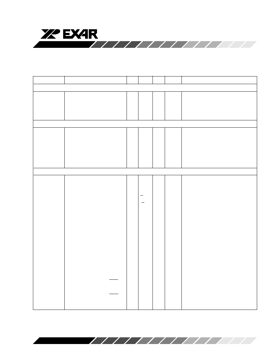
SHP, SHD and RSTCCD Signals, M2 = 0
The SHP input to the XRD9855/XRD98L55 determines
when the Black level of each pixel is sampled. For
CLK_POL=high timing mode, the black level is
sampled on the falling edge of SHP. For
CLK_POL=low timing mode, the black level is sampled
on the rising edge of SHP.
The sampling edge of SHP should be positioned so that
it samples the pixel black level at a stable and repeat-
able point. The black level should be sampled after the
CCD output has had time to settle from the reset pulse
and before the output transitions to the video level (see
Figure 8). Aperture delay T
BK
needs to be taken into
consideration when positioning the sampling edge of
SHP (see
Figure 8). This aperture delay is the time
from the sampling edge of SHP to the time the pixel
black level is actually sampled by the CDS. The
correct positioning of SHP will be 6-7 ns prior to where
the black level has adequately settled. This is typically
just before the CCD signal starts the transition to the
video level.
The SHD input to the XRD9855/XRD98L55 determines
when the Video level of each pixel is sampled. For
CLK_POL=high timing mode, the video level is
sampled on the falling edge of SHD. For
CLK_POL=low timing mode, the video level is sampled
on the rising edge of SHD.

XRD9855/L55
17
Rev. 1.00
Preliminary
SHP
SHD
CCD
Signal
RSTCCD
Pixel Black Level
Sample Point
Pixel Video Level
Sample Point
TBK
T VD
T RST
RSTCCD
Switch
Turn Off
Turn On
Reset Pulse
RSTCCD
Switch
Figure 8. CDS Timing Diagram
(CLK_POL = 1, M2 = 0)
The sampling edge of SHD should be positioned so that
it samples the pixel video level at a stable and repeat-
able point. The video level should be sampled after the
CCD output has settled from the black level and before
the output transitions to the reset pulse. Aperture
delay T
VD
needs to be taken into consideration when
positioning the sampling edge of SHD (see
Figure 8).
This aperture delay is the time from the sampling edge
of SHD to the time the pixel video level is actually
sampled by the CDS. The correct positioning of SHD
will be 5-6 ns prior to where the video level has
adequately settled.
RSTCCD is intended to overlap the reset pulse of each
pixel. This is intended to eliminate the reset pulse
transients from getting into the XRD9855's CDS cir-
cuitry. Positioning of the RSTCCD signal so that it
overlaps the CCD signal reset pulse is not always
practical due to the timing generators being used or the
frequency at which the CCD is running. The most
critical thing to remember for RSTCCD is that it can not
be high when sampling either the black level or video
level.
XRD9855/L55
18
Rev. 1.00
Preliminary
Data N
DB[9:0]
(Output)
SHP
SHD
CCD
Signal
Pixel N
RSTCCD
T
DL
Sample Pixel
Black Level
Data N-1
Sample Pixel
Video Level
Data N-2
Data N-3
Data N-4
Figure 9. Conversion Timing Diagram Showing Pipeline Delay
(CLK_POL = 1, M2 = 0)

XRD9855/L55
19
Rev. 1.00
Preliminary
CDS Clock Polarity
The CLK_POL pin is used to determine the polarity of
the CDS clocks (SHD, SHP, CLAMP). See
Figures 10
& 11, and Tables 7 & 8.
Event
Action
RSTCCD
Disconnect CDS Inputs from Reset
Noise
RSTCCD
Connect CDS Inputs and Track Black
Level
SHP
Hold Black Level and Track Video Level
SHD
Hold Video Level
SHP/SHD
No Action
Clamp High Activate DC Restore Clamp
Enable_Cal Activate Offset Calibration
High
Table 7. Timing Event Description
Table Valid for CLK_POL=1, M2=0
Event
Action
RSTCCD
Disconnect CDS Inputs from Reset
Noise
RSTCCD
Connect CDS Inputs and Track Black
Level
SHP
Hold Black Level and Track Video Level
SHD
Hold Video Level
SHP/SHD
No Action
Clamp Low
Activate DC Restore Clamp
Enable_Cal Activate Offset Calibration
High
Table 8. Timing Event Description
Table Valid for CLK_POL=0, M2=0
Line N
Line N+1
* Note: OB = Optically Black or Shielded pixels.
Active Video
Pixels
OB* pixels
Vertical Shift
Dummy &
OB* Pixels
EnableCal
Clamp
CCD Signal
RSTCCD
SHP
SHD
Active Video
Pixels
Figure 10. CCD Line Timing with CLK_POL = 1, M2 = 0
XRD9855/L55
20
Rev. 1.00
Preliminary
No RSTCCD Pulse Timing, M2 = 1
To help simplify the timing required to drive the
XRD9855 we have included a timing mode which does
not require an active signal for RSTCCD. To use this
timing, bit M2 in the timing mode register must be set
high.
In this timing mode, RSTCCD must be kept low. No
changes are required for the timing of the SHP and SHD
signals. The polarity of SHP, SHD and Clamp are still
controlled by the CLK_POL pin. The digital outputs
change on the sampling edge of SHD (see
Figure 12).
This mode can be used with both the XRD4460 timing
and the XRD9853 timing as described in the Line
Timing section.
Figure 12. XRD9855 Timing for no RSTCCD Pulse,
M2=1 & CLK_POL=1, RSTCCD=0
CCD Signal
RSTCCD
DB[9:0]
SHP
SHD
1
0
1
0
1
0
1
0
Pixel N
Data N-4
Data N-3
Data N-2
Data N-1
Data N
Line N
Line N+1
* Note: OB = Optically Black or Shielded pixels.
Active Video
Pixels
OB* Pixels
Vertical Shift
Dummy &
OB* Pixels
EnableCal
Clamp
CCD Signal
RSTCCD
SHP
SHD
Active Video
Pixels
CLK_POL=Low
Figure 11. CCD Line Timing with CLK_POL = 0, M2 = 0

XRD9855/L55
21
Rev. 1.00
Preliminary
Programmable Aperture Delays
Dp[2:0], Dd[2:0], Dr[1:0]
To help fine tune the pixel timing, the XRD9855 allows
the system to adjust the aperture delays associated
with SHP (T
BK
), SHD (T
VD
) and RSTCCD (T
RST
) by
programming the Aperture Delay serial port register.
On power up these three aperture delays are set to their
minimum values.
The SHP aperture delay is set by bits Dp[2:0]. Each
LSB adds approximately 2ns of delay. The SHD
aperture delay is set by bits Dd[2:0]. Each LSB adds
approximately 2ns of delay. The RSTCCD aperture
delay is set by bits Dr[1:0]. Each LSB adds approxi-
mately 4ns of delay.
Dp[2]
Dp[1]
Dp[0]
SHP Aperture
Delay T
BK
(typ)
0
0
0
6ns (default)
0
0
1
8ns
0
1
0
10ns
0
1
1
12ns
1
0
0
14ns
1
0
1
16ns
1
1
0
18ns
1
1
1
20ns
Table 9. Programmable SHP Delays
Dd[2]
Dd[1]
Dd[0]
SHD Aperture
Delay T
VD
(typ)
0
0
0
5ns (default)
0
0
1
7ns
0
1
0
9ns
0
1
1
11ns
1
0
0
13ns
1
0
1
15ns
1
1
0
17ns
1
1
1
19ns
Table 10. Programmable SHD Delays
Dr[1]
Dr[0]
RSTCCD Aperture
Delay T
RST
(typ)
0
0
3ns (default)
0
1
7ns
1
0
11ns
1
1
15ns
Table 11. Programmable RSTCCD Delays
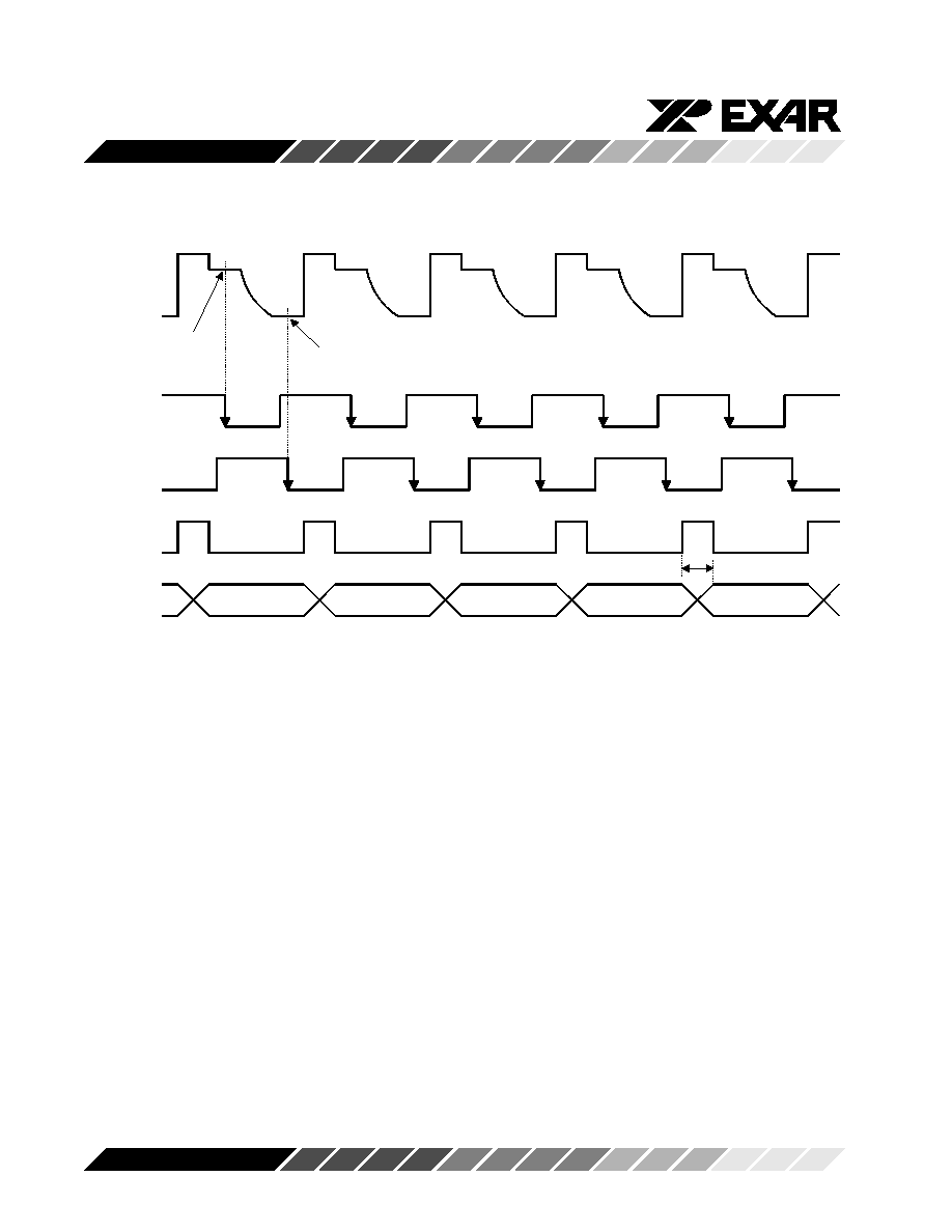
Line Timing
At the beginning and/or end of every CCD line there are
a number of Optical black pixels. The XRD9855 uses
the output from these pixels for the DC Restore Clamp
and Black Level Offset Calibration functions. These
functions are controlled by the Clamp and/or EnableCal
pins.
The XRD9855 is designed to be compatible with the
Clamp Only timing of the XRD4460 or the Clamp &
EnableCal timing of the XRD9853. On power up the
chip will automatically detect which timing is being
used and make the necessary internal adjustments. If
EnableCal is high when Clamp is active, then "Clamp
Only" timing is selected (M3=0). If EnableCal is low
when Clamp is active, then "Clamp & Cal" timing is
selected (M3=1). If required, the automatic detection
function can be disabled through the serial port, and the
chip can be forced into one of the two timing modes by
programming mode register bits M3 & M1.
Clamp Only Timing (XRD4460 compatible)
M1=1, M3=0
In this mode EnableCal is held high, and Clamp is
activated during the Optical Black pixels.
The Clamp signal is used to trigger a one-shot which
controls the internal DC restore switch and the calibra-
tion logic. The DC restore switch is turned on for two
pixels after Clamp is activated. Then the Calibration
logic is enabled and runs until Clamp is deactivated.
The chip can be forced into this timing mode by
programming the Mode control register bits M1=1 and
M3=0.

XRD9855/L55
22
Rev. 1.00
Preliminary
Figure 13. Clamp Only Line Timing
CLK_POL=1, EnableCal=1, M1=1, M3=0, M2=0
CCD
Input
DB[9:0]
ADC
Bias
Clamp
Clamp Only Mode
DC Restore
Switch
EnableCal
PGA
CDS
Clk_Pol
Control
Logic
Offset
Calibration
Figure 14. Clamp Only Mode (XRD4460 Compatible)
M1=1, M3=0
Line N
Line N+1
* Note: OB = Optically Black or Shielded pixels.
Signal
Pixels
OB* Pixels
Signal
Pixels
Vertical Shift
Dummy &
OB* Pixels
(Horizontal Clocking Off)
EnableCal
Clamp
CCD Signal
RSTCCD
SHP
SHD
1
0
1
0
1
0
1
0
1
0
Internal Calibrate
Internal DC
Restore Switch
1
0
1
0
Minimum 10 OB Pixels
2 OB Pixels

XRD9855/L55
23
Rev. 1.00
Preliminary
Optical
Black
Pixels
(Shielded)
Active Video
Pixels
Dummy
&
Optical
Black
Pixels
Clamp & EnableCal Timing (XRD9853 Compatible)
M1=1, M3=1
In this mode EnableCal must be active during the large
number of Optical Black pixels (usually at the end of
each CCD line), Clamp should be active during the
Dummy pixels (usually at the beginning of each CCD
line).
The EnableCal pin (always active high) directly con-
trols the calibration logic.
The Clamp pin (polarity determined by CLK_POL)
controls only the DC restore switch at the CDS input.
EnableCal and Clamp must not be active at the same
time.
The chip can be forced into this timing mode by
programming the Mode control register bits M1=1 and
M3=1.
Figure 16. Clamp & EnableCal Timing, CLK_POL=1, M1=1, M3=1, M2=0
Figure 15. Typical CCD Array with Active Pixels
& Optically Black Pixels
Line N
Line N+1
* Note: OB = Optically Black or Shielded Pixels.
Signal
Pixels
OB* Pixels
Signal
Pixels
Vertical Shift
Dummy &
OB Pixels
(Horizontal Clocking Off)
EnableCal
Clamp
CCD Signal
RSTCCD
SHP
SHD
Min. 2 Pixels
Min. 8 OB Pixels

XRD9855/L55
24
Rev. 1.00
Preliminary
Offset
Calibration
CCD
Input
DB[9:0]
ADC
bias
Clamp
Clamp & EnableCal Mode
EnableCal
PGA
CDS
Clk_Pol
DC Restore
switch
CDS/
Clock
Digital
STBY2
STBY1
PGA
ADC
Inputs
Outputs
0
0
Off
Off
Off
High-z
1
0
On
Off
On
High-z
0
1
Off
On
On
On
1
1
On
On
On
On
Figure 17. Clamp & Enable Cal Mode (XRD9853 Compatible),
M1=1, M3=3
Stand-by Mode (Power Down)
The STBY1 and STBY2 pins are used to put the chip
into the Stand-by or Power down mode. In this mode
all sampling and conversion stops, The digital outputs
are put into the high impedance mode, and the power
supply current will drop to less than 50
µ
A.
For most applications STBY1 and STBY2 should be
connected together and treated as a single control pin.
If an application uses the TestVin pin to access the
PGA output or the ADC input then STBY1 and STBY2
must be separately controlled, see the truth table
below.
Table 12. Stand-by Truth Table

XRD9855/L55
25
Rev. 1.00
Preliminary
Chip Reset
The chip has an Internal Power-On-Reset function to
ensure all internal control registers start up in a known
state. Pulling the Reset pin high or writing a logic 1 to
the Mode Registers reset bit will also reset the chip to
the Power-up default conditions.
Register
Default
Notes
Gain[7:0]
00000000
minimum gain
OS[7:0]
00001000
code 08 hex
V[1:0]
01
25 mV offset
M3
0
Clamp only
M2
0
RSTCCD required
M1
0
Automatic timing detect On
Test3
0
Test modes off
Test2
0
Test modes off
Reset
0
reset bit will reset itself
Dp[2:0]
000
minimum delay
Dd[2:0]
000
minimum delay
Dr[1:0]
00
minimum delay
Table 13. Reset Conditions
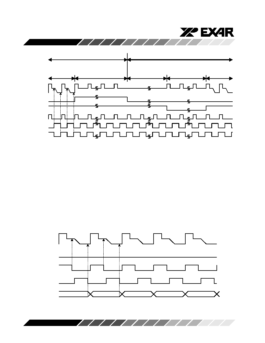
Using TestVin (Pin 20)
The TestVin pin allows access to the input of the ADC,
or it can be used to monitor the CDS/PGA output. The
TestVin pin accesses the ADC input node through
switch S1 (see
Figure 18). This switch is controlled by
Bit3 of the serial port Test register. When the TEST3
bit of the mode register is high, switch S1 is "ON" and
the TestVin pin can be used to access the ADC input/
PGA output. When the TEST3 bit of the mode register
is low, switch S1 is "OFF" and the TestVin pin is
disconnected from the ADC input/PGA output.
To use TestVin as an auxiliary ADC input force
STBY2=low and STBY1=high. This will disable the
CDS/PGA and leave the ADC operating. If M2=0, the
ADC clock is generated from RSTCCD and SHP (
See
Figure 19). If M2=1, the ADC clock is generated from
SHP & SHD (
See Figure 20).

XRD9855/L55
26
Rev. 1.00
Preliminary
Mode Reg.
AD1
AD0
V[1]
V[0]
M3
M2
Test3
Test2
M1
Reset
TestVin
1
0
0
0
0
1
1
0
0
0
Normal
1
0
0
0
0
1
0
0
0
0
Table 14. Serial Port Data to Use TestVin
Figure 18. Using TestVin to Access PGA Output & ADC Input
CDS
PGA
ADC
S1
TestVin
CCD
Signal
RSTCCD
SHP
SHD
ADC Clock
(internal)
Track
Hold
ADC Data
CCD
Signal
RSTCCD
SHP
SHD
ADC Clock
(Internal)
Track
Hold
ADC Data
Figure 19. ADC Clock Generation,
CLK_POL=1, M2=0
Figure 20. ADC Clock Generation,
CLK_POL=1, M2=1

XRD9855/L55
27
Rev. 1.00
Preliminary
Digital Output Power Supplies
The DV
DD
and DGND pins supply power to the digital
output drivers for pins DB[9:0], UNDER, and OVER.
DV
DD
is isolated from V
DD
so it can be at a voltage
level less than or equal to V
DD
. This allows the digital
outputs to interface with advanced digital ASICs requir-
ing reduced supply voltages. For example V
DD
can be
5.0 or 3.3V, while DV
DD
is 2.5V.
Systems which use the same voltage level for both
analog and digital power supplies can take advantage
of the isolated DV
DD
& DGND pins to reduce system
noise. The output drivers create large supply tran-
sients as they switch. Therefore DV
DD
and DGND
should be routed separately from the analog V
DD
&
GND to avoid injecting this noise into the analog power
network (see
Figure 21.)
Output
Register
V
DD
DV
DD
DGND
GND
Digital Output
Source-Body
Junction Diode
Between DV
DD
& V
DD
Source-Body
Junction Diode
Between
DGND & GND
Figure 21. DV
DD
& DGND Digital Output Power Supplies,
V
DD
> DV
DD
There are no power supply sequencing issues if DV
DD
and V
DD
of the XRD9855/98L55 are driven from the
same supply. When DV
DD
and V
DD
are driven
separately, V
DD
must come up at the same time or
before DV
DD
, and go down at the same time or after
DV
DD
. If the power supply sequencing in this case is
not followed, then damage may occur to the product due
to current flow through the source-body junction diodes
between DV
DD
and V
DD
. An external diode (5082-
2235) layed out close to the converter from DV
DD
to
V
DD
prevents damage from occurring when power is
cycled incorrectly.
Note: V
DD
must be greater than or equal to DV
DD
or the
source-body diodes will be forward based.
Power Supply Sequencing

XRD9855/L55
28
Rev. 1.00
Preliminary
All of the GND pins, other than DGND, are tied to the
substrate and should be connected directly to the
analog ground plane under the XRD9855/XRD98L55.
The V
DD
's should be supplied from a low noise, well
filtered regulator which derives the power supply volt-
age from the CCD power supply. All of the V
DD
pins are
analog power supplies and should be locally decoupled
to the nearest GND pin with a 0.1
µ
F, high frequency
capacitor. DV
DD
and DGND are the power supplies for
the digital outputs and should be locally decoupled.
DV
DD
and DGND should be connected to the same
power supply network as the digital ASIC which re-
ceives data from the XRD9855/XRD98L55.
In general, all traces leading to the XRD9855/
XRD98L55 should be as short as possible to minimize
signal crosstalk and high frequency digital signals from
feeding into sensitive analog inputs. The two CCD
inputs, In_Pos and In_Neg, should be routed as fully
differential signals and should be shielded and
matched. Efforts should be made to minimize the board
leakage currents on In_Pos and In_Neg since these
nodes are AC coupled from the CCD to the XRD9855/
XRD98L55. The digital output traces should be as short
as possible to minimize the capacitive loading on the
output drivers (see
Figure 22.)
General Power Supply and Board Design Issues
CCD
12V
5V/3V
Regulator
V
DD
DV
DD
In_Neg
In_Pos
GND
DB[9:0]
DGND
XRD9855/XRD98L55
DV
DD
Digital
ASIC
DGND
5V/3V
Regulator
AGND
DGND
Figure 22. XRD9855/XRD98L55 Power Supply Connections
Application Note
If increasing the PGA Gain to code 128 (80h) or higher
causes a larger than expected offset increase in the
ADC digital output codes, the problem may be due to
the limited Automatic Offest Calibration range. This
problem may be solved by increasing the Global Offset
code, V[1:0], in the Mode Register. The default is
V[1:0] = 01 (binary). Try increasing to V[1:0] = 10, or
V[1:0] = 11.

XRD9855/L55
29
Rev. 1.00
Preliminary
Figure 23. XRD9855/XRD98L55 Application Schematic
CLK_POL=0
1
26
12
36
23
13
38
48
DB2
DB3
DB4
DGND
DB5
DB6
DB7
DB8
DB9
14
15
16
17
2
3
4
5
6
7
8
9
10
11
18
19
20
21
22
24
25
27
28
29
30
31
32
33
34
35
37
39
40
41
42
43
44
45
46
47
OVER
OE
V
DD
EnableCal
GND
Test
STBY1
STBY2
RESET
SCLK
LOAD
SDI
V
RT
V
RTO
V
RB
In_Neg
In_Pos
GND
V
RBO
CLAMP
SHD
SHP
RSTCCD
GND
CLK_POL
V
DD
SYNC
UNDER
DB0
DB1
XRD9855/XRD98L55
Digital Data Bus
V
DD
Serial
Interface
V
DD
V
DD
to CCD
Signal
to CCD
Ground
V
DD
From Clock
Signal
Generator
0.01
µ
F
0.01
µ
F
0.01
µ
F
DV
DD
V
DD
0.1
µ
F
0.1
µ
F
0.1
µ
F
from Clock Signal
Generator
0.1
µ
F
NC
NC
NC
NC
NC
DV
DD

XRD9855/L55
30
Rev. 1.00
Preliminary

XRD9855/L55
31
Rev. 1.00
Preliminary
Notes

XRD9855/L55
32
Rev. 1.00
Preliminary
NOTICE
EXAR Corporation reserves the right to make changes to the products contained in this publication in order to improve
design, performance or reliability. EXAR Corporation assumes no responsibility for the use of any circuits described
herein, conveys no license under any patent or other right, and makes no representation that the circuits are free of
patent infringement. Charts and schedules contained here in are only for illustration purposes and may vary depending
upon a user's specific application. While the information in this publication has been carefully checked; no
responsibility, however, is assumed for in accuracies.
EXAR Corporation does not recommend the use of any of its products in life support applications where the failure
or malfunction of the product can reasonably be expected to cause failure of the life support system or to significantly
affect its safety or effectiveness. Products are not authorized for use in such applications unless EXAR Corporation
receives, in writing, assurances to its satisfaction that: (a) the risk of injury or damage has been minimized; (b) the
user assumes all such risks; (c) potential liability of EXAR Corporation is adequately protected under the
circumstances.
Copyright 1998 EXAR Corporation
Datasheet December 1998
Reproduction, in part or whole, without the prior written consent of EXAR Corporation is prohibited.