
6.8
9.
2
1
2
3
3.4
2.
5
1.0
2.54
2.54
6.8
0.5
13.1
0.
4
7.
76
1 OUTPUT
2 GND
3 Vcc
6.
0
0.
3
EVERLIGHT ELECTRONICS CO., LTD.
Device Number: DMO-870-008 REV: 1.1
MODEL NO:
IRM-8755
ECN:
Page: 1/8
PACKAGE DIMENSIONS
Office: NO 25,Lane.76, Chung Yang Rd., Sec.3, Tucheng, Taipei 236, Taiwan, R.O.C.
TEL: 886-2-2267-2000,2267-9936(22Lines)
FAX: 886-2-2267-6189
http: //www.everlight.com

EVERLIGHT ELECTRONICS CO., LTD.
Device Number: DMO-870-008 REV: 1.1
MODEL NO:
IRM-8755
ECN:
Page: 2/8
NOTES
1. This drawing measure is a standard value. All dimensions are in millimeter.
2. In case of designation is tolerance ± 0.3mm.
3. Lead spacing is measured where the lead emerge from the package.
4. Protruded resin under flange 1.0mm Max.
5. Lens color: Black.
6. Above specification may be changed without notice. EVERLIGHT will reserve authority
on material change for above specification.
7. These specification sheets include materials protected under copyright of EVERLIGHT
corporation. Please don't reproduce or cause anyone to reproduce them without
EVERLIGHT consent.
8. When using this produce, please observe the absolute maximum ratings and the
instructions for use outlined in these specification sheets. EVERLIGHT assumes no
responsibility for any damage resulting from use of the product which does not comply
with the absolute maximum ratings and the instructions included in these specification
sheets.
Description
The device is a miniature type infrared remote control system receiver which has been
developed and designed by utilizing the most updated IC technology. The PIN diode and
preamplifier are assembled on lead frame, the epoxy package is designed as an IR filter.
The demodulated output signal can directly be decoded by a microprocessor.
Feature
1.
High protection ability to EMI and metal case can be customized.
2.
Mold type and metal case type to meet the design of front panel.
3.
Elliptic lens to improve the characteristic against
4.
Line-up for various center carrier frequencies.
5.
Low voltage and low power consumption.
6.
High immunity against ambient light.
7.
Photodiode with integrated circuit.
8.
TTL and CMOS compatibility.
9.
Long reception distance.
10.
High sensitivity.
EVERLIGHT ELECTRONICS CO., LTD.
Device Number: DMO-870-008 REV: 1.1
MODEL NO:
IRM-8755
ECN:
Page: 3/8
Application
1.
Optical switch
2.
Light detecting portion of remote control
·
AV instruments such as Audio, TV, VCR, CD, MD, etc.
·
Home appliances such as Air-conditioner, Fan , etc.
·
The other equipments with wireless remote control.
·
CATV set top boxes
·
Multi-media Equipment
Absolute maximum ratings (Ta=25)
Parameter
Symbol
Ratings
Unit
Notice
Supply Voltage
Vcc
0~6
V
Operating Temperature
Topr
-30+85
Storage Temperature
Tstg
-40+85
Soldering Temperature
Tsol
260
4mm from mold body
less than 5 seconds
Electro Optical Characteristics (Ta=25)
Parameter
Symbol
MIN
TYP
MAX
Unit
Condition
Supply Voltage
Vcc
4.5
5
5.5
V
DC voltage
Supply Current
Icc
-
-
3
mA
No signal input
B.P.F Center Frequency
fo
-
38
-
KHz
Peak Wavelength
p
-
940
-
nm
L
0
8
-
-
At the ray axis
Transmission Distance
L
45
4
-
m
*1
Half Angle (Horizontal)
h
-
4
5
-
deg
Half Angle (Vertical)
v
-
35
-
deg
High Level Pulse Width
TH
400
-
800
µ
s
Low Level Pulse Width
TL
400
-
800
µ
s
At the ray axis
*2
High Level Output
Voltage
VH
4.5
-
-
V
Low Level Output
Voltage
VL
-
0.2
0.5
V

EVERLIGHT ELECTRONICS CO., LTD.
Device Number: DMO-870-008 REV: 1.1
MODEL NO:
IRM-8755
ECN:
Page: 4/8
*1:The ray receiving surface at a vertex and relation to the ray axis in the
range of
= 0
°
and
=45
°
.
*2:A range from 30cm to the arrival distance. Average value of 50 pulses.
TEST METHOD
The specified electro-optical characteristics is satisfied under the following
Conditions at the controllable distance.
Measurement place
A place that is nothing of extreme light reflected in the room.
External light
Project the light of ordinary white fluorescent lamps which are not high
Frequency lamps and must be less then 10 Lux at the module surface.
(Ee10Lux)
Standard transmitter
A transmitter whose output is so adjusted as to
Vo=400mVp-p
and the output
Wave form shown in Fig.-1.According to the measurement method shown in
Fig.-2 the standard transmitter is specified.
However , the infrared photodiode to be used for the transmitter should be
p=940nm,
=50nm. Also, photodiode is used of PD438B(Vr=5V).
(Standard light / Light source temperature 2856
°
K).
Measuring system
According to the measuring system shown in Fig.-3
Carrier frequency is adjusted to
center frequency of each product.
IR TANSMITTER
OUTPUT WAVE FORM
OUTPUT PULSE
OF DEVICE
D.U.T
L: Transmission Distance
Standard Transmitter
GND
Vcc
OUT
Vout
: Angle Of Horizontal & Vertical Direction
Standard Transmitter
Oscilloscope
Vout
10uF
+5.0± 0.1V
10k
20cm
100k
EVERLIGHT ELECTRONICS CO., LTD.
Device Number: DMO-870-008
REV:
1.1
MODEL NO:
IRM-8755
ECN:
Page: 5/8
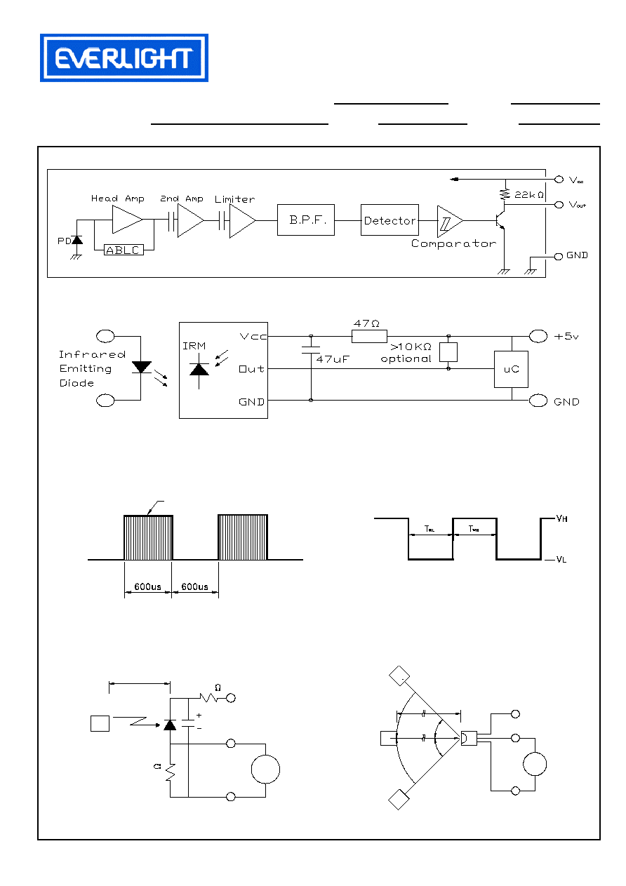
Block Diagram
Application Circuit
RC Filter should be connected closely between Vcc pin and GND pin.
Fig.-1 Transmitter Wave Form
D.U.T output Pulse
Fig.-2 Measuring Method
Fig.-3 Measuring System
Duty=0.5