
522 Almanor Ave., Sunnyvale, CA 94086
Phone: (800) SMI-MMIC
http://www.stanfordmicro.com
Preliminary
EDS-101241 Rev A
Product Description
1
Preliminary
SHF-0289
DC-3 GHz, 1.0 Watt
GaAs HFET
Product Features
·
Patented GaAs Heterostructure FET
Technology
·
+30dBm Output Power at 1dB Compression
·
+46dBm Output IP3
·
High Drain Efficiency: Up to 40% at Class AB
·
13 dB Gain at 900MHz (Application circuit)
·
13 dB Gain at 1900MHz (Application circuit)
Applications
·
Analog and Digital Wireless System
·
Cellular PCS, CDPD, Wireless Data, Pagers
Electrical Specifications at Ta = 25
o
C
Stanford Microdevices' SHF-0289 series is a high performance
GaAs Heterostructure FET housed in a low-cost surface-mount
plastic package. HFET technology improves breakdown voltage
while minimizing Schottky leakage current for higher power added
efficiency and improved linearity.
Output power at 1dB compression for the SHF-0289 is +30dBm
when biased for Class AB operation at 8V and 250mA. The
+46 dBm third order intercept makes it ideal for high dynamic
range, high intercept point requirements. They are well suited
for use in both analog and digital wireless communication
infrastructure and subscriber equipment including cellular PCS,
CDPD, wireless data, and pagers.
Adequate heat sinking must be provided for this part to avoid
exceeding the maximum junction temperature. Methods include
the use of screws near the device, and filled vias beneath the
part to the ground plane. Refer to "Mounting and Thermal
Considerations" section on page 7 for more information.
The information provided herein is believed to be reliable at press time. Stanford Microdevices assumes no responsibility for inaccuracies or omissions.
Stanford Microdevices assumes no responsibility for the use of this information, and all such information shall be entirely at the user's own risk. Prices and specifications are subject to change
without notice. No patent rights or licenses to any of the circuits described herein are implied or granted to any third party. Stanford Microdevices does not authorize or warrant any Stanford
Microdevices product for use in life-support devices and/or systems.
Copyright 2000 Stanford Microdevices, Inc. All worldwide rights reserved.
Frequency (GHz)
0
5
10
15
20
25
30
0
0.5
1
1.5
2
2.5
3
3.5
4
4.5
G
Max
(dB)
Maximum Available Gain vs Frequency
Vds = 8V, Idq = 250mA
l
o
b
m
y
S
s
n
o
i
t
i
d
n
o
C
t
s
e
T
:
s
r
e
t
e
m
a
r
a
P
s
t
i
n
U
.
n
i
M
.
p
y
T
.
x
a
M
S
|
1
2
|
2
n
i
a
G
r
e
w
o
P
n
o
it
r
e
s
n
I
Z
,
A
m
0
5
2
=
q
d
I
,
V
0
.
8
=
s
d
V
S
Z
=
L
s
m
h
O
0
5
=
z
H
G
9
.
0
=
f
z
H
G
9
.
1
=
f
B
d
7
.
7
1
5
.
2
1
G
x
a
m
n
i
a
G
e
l
b
a
li
a
v
A
m
u
m
i
x
a
M
Z
,
A
m
0
5
2
=
q
d
I
,
V
0
.
8
=
s
d
V
S
Z
=
T
P
O
S
Z
,
L
Z
=
T
P
O
L
z
H
G
9
.
0
=
f
z
H
G
9
.
1
=
f
B
d
3
2
0
2
P
I
O
T
t
n
i
o
P
t
p
e
c
r
e
t
n
I
r
e
d
r
O
d
r
i
h
T
t
u
p
t
u
O
)
t
u
p
t
u
o
r
e
w
o
p
m
u
m
i
x
a
m
r
o
f
d
e
n
u
t
s
i
e
c
i
v
e
D
(
z
H
G
9
.
0
=
f
z
H
G
9
.
1
=
f
m
B
d
m
B
d
6
4
6
4
I
s
s
D
t
n
e
r
r
u
C
n
i
a
r
D
d
e
t
a
r
u
t
a
S
V
0
=
s
g
V
,
V
0
.
3
=
s
d
V
A
m
0
5
6
G
m
:
e
c
n
a
t
c
u
d
n
o
c
n
a
r
T
V
0
=
s
g
V
,
V
0
.
3
=
s
d
V
S
m
5
7
3
p
V
:
e
g
a
tl
o
V
ff
O
-
h
c
n
i
P
A
m
2
.
1
=
d
I
,
V
0
.
2
=
s
d
V
V
7
.
2
-
9
.
1
-
0
.
1
-
V
s
g
b
A
m
4
.
2
=
s
g
I
,
e
g
a
tl
o
V
n
w
o
d
k
a
e
r
B
e
c
r
u
o
S
-
o
t
-
e
t
a
G
V
2
2
-
7
1
-
V
d
g
b
A
m
4
.
2
=
d
g
I
,
e
g
a
tl
o
V
n
w
o
d
k
a
e
r
B
n
i
a
r
D
-
o
t
-
e
t
a
G
V
2
2
-
7
1
-
h
t
R
d
a
e
l-
o
t
-
n
o
it
c
n
u
j
,
e
c
n
a
t
s
i
s
e
R
l
a
m
r
e
h
T
o
W
/
C
7
3
2
522 Almanor Ave., Sunnyvale, CA 94086
Phone: (800) SMI-MMIC
http://www.stanfordmicro.com
Preliminary
EDS-101241 Rev A
SHF-0289 DC-3GHz, 1 Watt GaAs HFET
Preliminary
Absolute Maximum Ratings
Notes:
1. Operation of this device above any one of these parameters
may cause permanent damage.
r
e
t
e
m
a
r
a
P
l
o
b
m
y
S
e
t
u
l
o
s
b
A
m
u
m
i
x
a
M
e
g
a
tl
o
V
e
c
r
u
o
S
-
o
t-
n
i
a
r
D
V
S
D
V
2
1
+
e
g
a
tl
o
V
e
c
r
u
o
S
-
o
t-
e
t
a
G
V
S
G
V
0
o
t
V
5
-
e
r
u
t
a
r
e
p
m
e
T
g
n
it
a
r
e
p
O
T
P
O
C
°
5
8
+
o
t
C
5
4
-
r
e
w
o
P
t
u
p
n
I
F
R
P
N
I
W
m
0
0
2
e
r
u
t
a
r
e
p
m
e
T
l
e
n
n
a
h
C
T
H
C
C
°
5
7
1
+
e
r
u
t
a
r
e
p
m
e
T
e
g
a
r
o
t
S
T
G
T
S
C
°
5
7
1
+
o
t
5
6
-
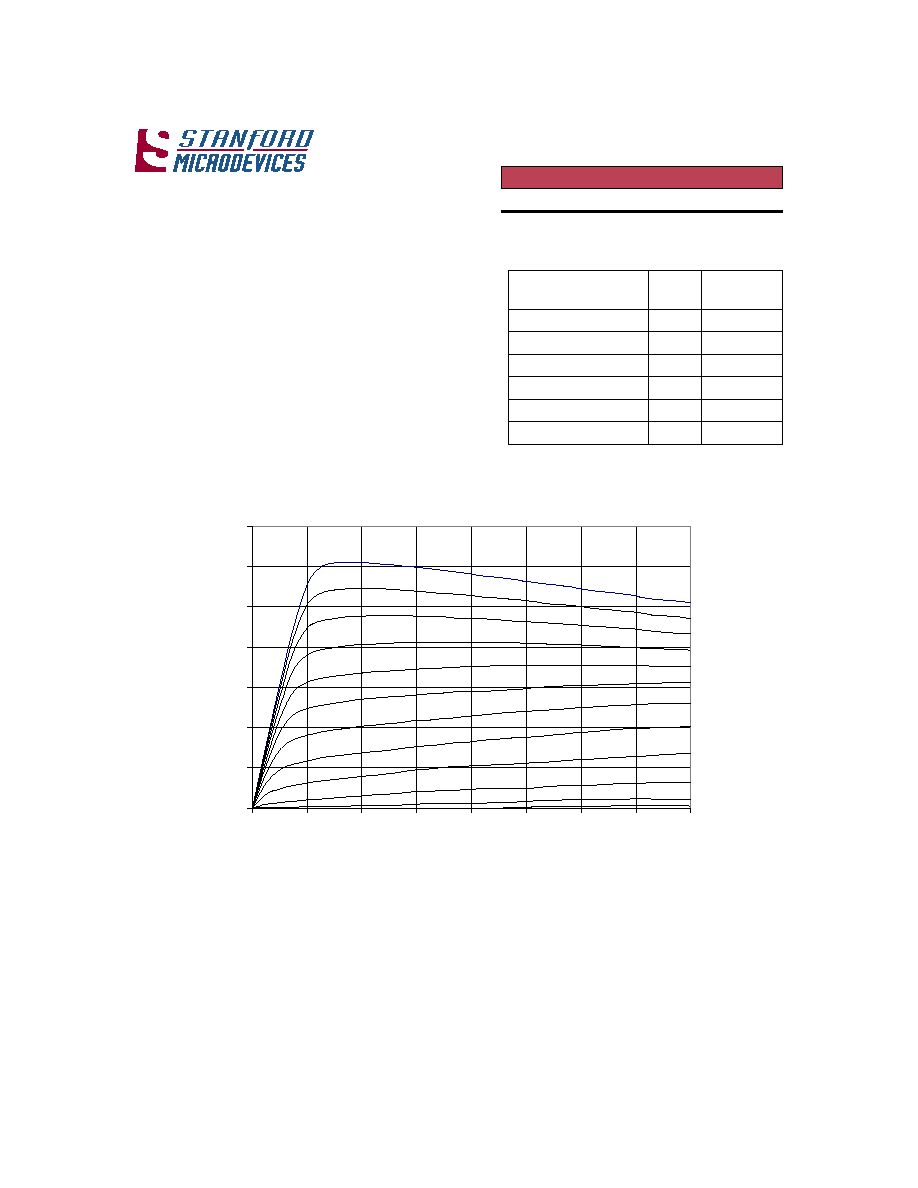
NOTE: I/V curves were taken using pulse sampling techniques. This
results in low duty cycle currents through the device and therefore very
low power levels. It is not recommended that these measurements be
taken in d.c. mode, as excessive current could result in damage to the
device.
Plot of I
D
vs. V
DS
for V
GS
= -2.2V to 0V
V
DS
(Volts)
I
D
(amps
)
0
0.1
0.2
0.3
0.4
0.5
0.6
0.7
0
1
2
3
4
5
6
7
8
V
GS
= 0 V
V
GS
= - 0.2 V
V
GS
= - 0.4
V
V
GS
= - 0.6 V
V
GS
= - 0.8 V
V
GS
= - 1.0 V
V
GS
= - 1.2 V
V
GS
= -1.4 V
V
GS
= -1.6 V
V
GS
= -1.8
V
V
GS
= -2.0 V
V
GS
= -2.2 V
3
522 Almanor Ave., Sunnyvale, CA 94086
Phone: (800) SMI-MMIC
http://www.stanfordmicro.com
Preliminary
EDS-101241 Rev A
SHF-0289 DC-3GHz, 1 Watt GaAs HFET
Preliminary
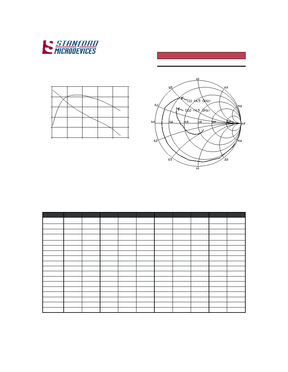
|S
21
| & |S
12
| vs. Frequency
GHz
dB
0
5
10
15
20
25
0
1
2
3
4
5
-40
-37
-34
-31
-28
-25
S
21
S
12
Typical s-parameters at 25
°°
°°
° C (V
ds
= 8V, I
dq
= 250mA)
z
H
G
q
e
r
F
S
|
1
1
|
S
1
1
g
n
A
S
1
2
B
d
S
|
1
2
|
S
1
2
g
n
A
S
2
1
B
d
S
|
2
1
|
S
2
1
g
n
A
S
|
2
2
|
S
2
2
g
n
A
5
0
.
0
8
9
.
0
9
.
7
2
-
2
.
3
2
4
.
4
1
5
.
2
6
1
5
.
6
3
-
2
0
.
0
4
.
2
7
0
2
.
0
6
.
7
4
-
1
.
0
8
9
.
0
9
.
3
3
-
9
.
2
2
0
.
4
1
5
.
8
5
1
6
.
5
3
-
2
0
.
0
0
.
9
6
0
2
.
0
3
.
2
5
-
3
.
0
5
9
.
0
0
.
8
5
-
8
.
1
2
3
.
2
1
8
.
2
4
1
6
.
2
3
-
2
0
.
0
0
.
5
5
3
2
.
0
3
.
1
7
-
5
.
0
1
9
.
0
2
.
2
8
-
5
.
0
2
6
.
0
1
1
.
7
2
1
4
.
0
3
-
3
0
.
0
0
.
1
4
5
2
.
0
2
.
0
9
-
7
.
0
8
8
.
0
2
.
4
0
1
-
1
.
9
1
0
.
9
6
.
2
1
1
0
.
9
2
-
4
0
.
0
4
.
8
2
7
2
.
0
5
.
8
0
1
-
9
.
0
6
8
.
0
5
.
1
2
1
-
7
.
7
1
7
.
7
6
.
0
0
1
2
.
8
2
-
4
0
.
0
4
.
8
1
8
2
.
0
5
.
1
2
1
-
1
.
1
5
8
.
0
4
.
5
3
1
-
5
.
6
1
7
.
6
3
.
0
9
8
.
7
2
-
4
0
.
0
2
.
0
1
0
3
.
0
5
.
1
3
1
-
3
.
1
5
8
.
0
9
.
6
4
1
-
3
.
5
1
8
.
5
3
.
1
8
6
.
7
2
-
4
0
.
0
0
.
3
1
3
.
0
6
.
9
3
1
-
5
.
1
4
8
.
0
8
.
6
5
1
-
3
.
4
1
2
.
5
9
.
2
7
5
.
7
2
-
4
0
.
0
2
.
3
-
2
3
.
0
8
.
6
4
1
-
7
.
1
4
8
.
0
4
.
5
6
1
-
3
.
3
1
6
.
4
2
.
5
6
5
.
7
2
-
4
0
.
0
8
.
8
-
3
3
.
0
2
.
3
5
1
-
9
.
1
4
8
.
0
1
.
3
7
1
-
5
.
2
1
2
.
4
9
.
7
5
5
.
7
2
-
4
0
.
0
1
.
4
1
-
4
3
.
0
7
.
9
5
1
-
1
.
2
4
8
.
0
9
.
9
7
1
6
.
1
1
8
.
3
8
.
0
5
6
.
7
2
-
4
0
.
0
7
.
8
1
-
5
3
.
0
6
.
5
6
1
-
3
.
2
4
8
.
0
8
.
3
7
1
8
.
0
1
5
.
3
2
.
4
4
8
.
7
2
-
4
0
.
0
2
.
3
2
-
6
3
.
0
7
.
1
7
1
-
5
.
2
4
8
.
0
6
.
7
6
1
8
.
9
1
.
3
8
.
7
3
2
.
8
2
-
4
0
.
0
2
.
7
2
-
0
4
.
0
2
.
6
7
1
-
0
.
3
5
8
.
0
3
.
4
5
1
2
.
8
6
.
2
9
.
2
2
7
.
8
2
-
4
0
.
0
8
.
5
3
-
3
4
.
0
6
.
4
7
1
5
.
3
1
8
.
0
5
.
4
4
1
3
.
6
1
.
2
3
.
9
7
.
9
2
-
3
0
.
0
7
.
3
4
-
0
5
.
0
2
.
4
6
1
0
.
4
7
7
.
0
6
.
4
3
1
0
.
4
6
.
1
3
.
4
-
9
.
0
3
-
3
0
.
0
5
.
1
5
-
6
5
.
0
9
.
3
5
1
5
.
4
3
7
.
0
8
.
4
2
1
9
.
0
1
.
1
9
.
7
1
-
2
.
2
3
-
2
0
.
0
4
.
9
5
-
2
6
.
0
5
.
3
4
1
S
11
& S
22
vs. Frequency (.05 to 4.5 GHz)
Frequency (GHz)
S
21
(dB
)
S
12
(dB)
No external matching, scattering parameters de-embedded on test fixture to device lead at
package edge.
4
522 Almanor Ave., Sunnyvale, CA 94086
Phone: (800) SMI-MMIC
http://www.stanfordmicro.com
Preliminary
EDS-101241 Rev A
SHF-0289 DC-3GHz, 1 Watt GaAs HFET
Preliminary
-3 0
-2 5
-2 0
-1 5
-1 0
-5
0
0 .7
0 .8
0 .9
1 .0
1 .1
6
9
1 2
1 5
1 8
0 .7
0 .8
0 .9
1 .0
1 .1
- 3 8
- 3 5
- 3 2
- 2 9
- 2 6
Frequency GHz
Note: s-parameters determined using applications circuit shown above
Frequency GHz
S
11
S
22
S
12
S
21
10
20
30
40
0
5
10
15
20
Test Data @ 0.9 GHz
P
1dB
(dBm) IP3(dBm) Output tone Level (dBm)
30.5 46.0 15
.
g
i
s
e
d
.f
e
R
e
u
l
a
V
e
l
y
t
S
/
r
e
b
m
u
N
t
r
a
P
7
,
1
d
C
F
p
0
2
2
s
e
i
r
e
s
8
1
H
C
M
M
H
O
R
2
1
,
8
,
6
,
2
d
C
F
p
8
1
s
e
i
r
e
s
8
1
H
C
M
M
H
O
R
0
1
,
3
d
C
F
p
0
0
0
1
s
e
i
r
e
s
8
1
H
C
M
M
H
O
R
9
,
4
d
C
F
p
0
0
1
s
e
i
r
e
s
8
1
H
C
M
M
H
O
R
1
1
,
5
d
C
F
u
1
.
0
tl
o
v
5
3
,
"
A
"
e
z
i
s
,
M
U
L
A
T
N
A
T
1
M
C
F
p
3
.
3
s
e
i
r
e
s
8
1
H
C
M
M
H
O
R
2
M
C
F
p
9
.
3
s
e
i
r
e
s
8
1
H
C
M
M
H
O
R
1
M
L
H
n
6
.
5
K
6
N
5
H
F
-
8
0
6
1
L
L
O
K
O
T
2
M
L
H
n
7
.
4
K
7
N
4
H
F
-
8
0
6
1
L
L
O
K
O
T
1
s
a
i
b
L
H
n
9
3
T
N
9
3
H
F
-
8
0
6
1
L
L
O
K
O
T
2
s
a
i
b
L
H
n
2
8
T
N
2
8
H
F
-
8
0
6
1
L
L
O
K
O
T
2
,
1
b
a
t
s
R
s
m
h
o
0
2
3
0
6
0
e
z
i
s
.
g
i
s
e
d
.
f
e
R
e
u
l
a
V
1
Z
z
H
M
0
0
9
@
.
g
e
d
0
.
6
,
s
m
h
o
0
5
2
Z
z
H
M
0
0
9
@
.
g
e
d
7
.
2
,
s
m
h
o
0
5
3
Z
z
H
M
0
0
9
@
.
g
e
d
5
.
8
,
s
m
h
o
0
5
4
Z
z
H
M
0
0
9
@
.
g
e
d
8
.
3
,
s
m
h
o
0
5
5
Z
z
H
M
0
0
9
@
.
g
e
d
4
.
3
,
s
m
h
o
0
5
6
Z
z
H
M
0
0
9
@
.
g
e
d
2
.
2
,
s
m
h
o
0
5
7
Z
z
H
M
0
0
9
@
.
g
e
d
0
.
6
,
s
m
h
o
0
5
8
Z
z
H
M
0
0
9
@
.
g
e
d
7
.
2
,
s
m
h
o
0
5
0
2 0
4 0
6 0
1 5
2 0
2 5
3 0
3 5
2 7 0
3 5 0
4 3 0
5 1 0
D ra in E ffic ie n c y
I
D
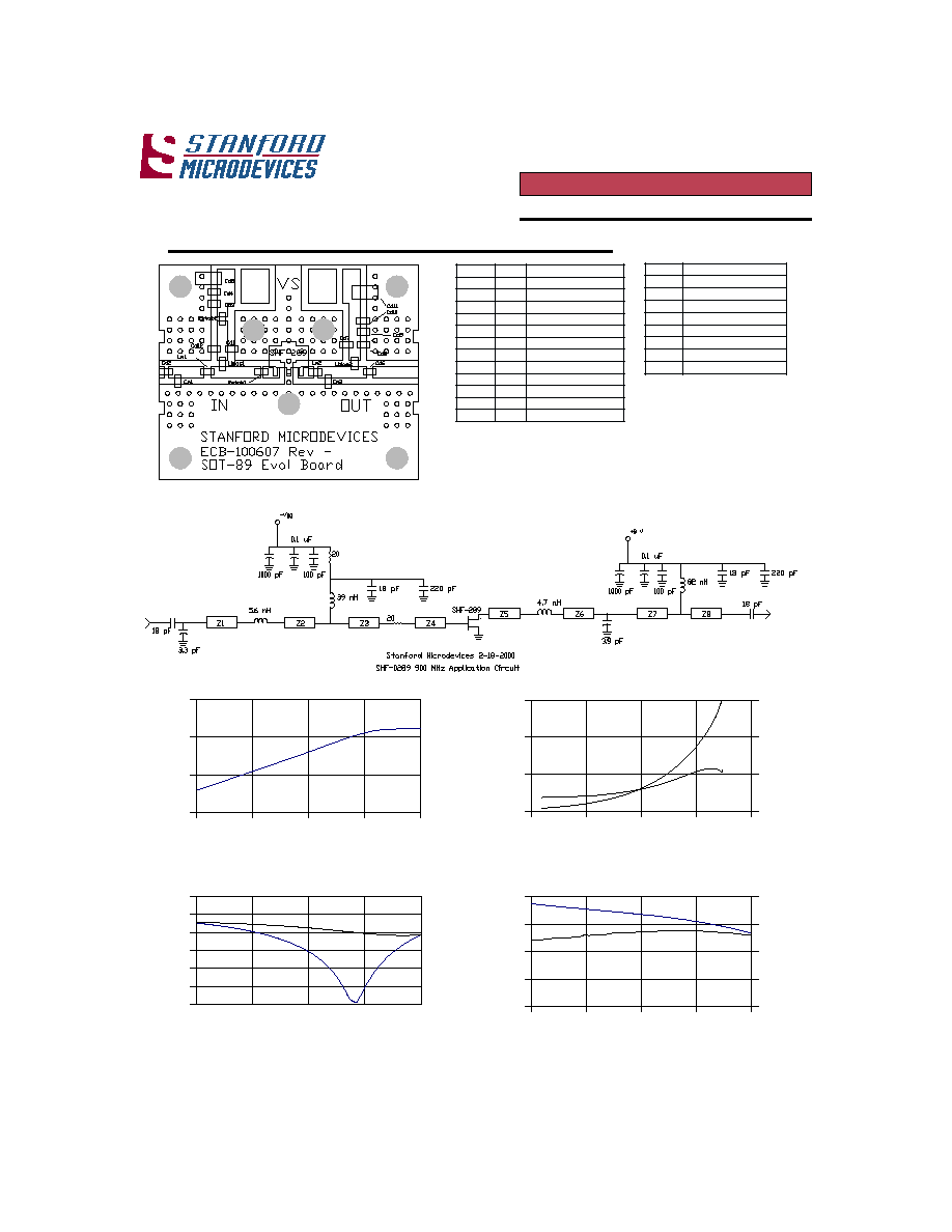
900 MHz Application Circuit at 25
°°
°°
° C (Vds=8V, Idq=250mA)
P
hase shift functional block between compo-
nents are calculated based on wavelength of 900
MHz signal on FR4 board material with dielec-
tric constant of 4.1, microstrip width and height
dimensions of W=.054 inch and h= .031 inch.
Microstrip Segment Specifications
P
out
(dBm)
P
out
vs. P
in
T=25
°°
°°
°
C
Drain Efficiency & I
D
vs. P
out
T=25
°°
°°
°
C
E
f
ficiency (%)
P
in
(dBm)
I
D
(mA)
S
11
, S
22
(dB)
S
21
(dB)
S
12
(dB)
S
11
& S
22
vs. Frequency T=25
°°
°°
°
C
S
21
& S
12
vs. Frequency T=25
°°
°°
°
C
P
out
(dBm)

5
522 Almanor Ave., Sunnyvale, CA 94086
Phone: (800) SMI-MMIC
http://www.stanfordmicro.com
Preliminary
EDS-101241 Rev A
SHF-0289 DC-3GHz, 1 Watt GaAs HFET
Preliminary
6
9
1 2
1 5
1 8
1 .5
1 .7
1 .9
2 .1
2 .3
- 3 8
- 3 5
- 3 2
- 2 9
- 2 6
-3 0
-2 5
-2 0
-1 5
-1 0
-5
0
1 .5
1 .7
1 .9
2 .1
2 .3
Frequency GHz
Frequency GHz
S
11
S
12
S
21
1 0
2 0
3 0
4 0
0
5
1 0
1 5
2 0
Pin (dBm)
Note: s-parameters determined using applications circuit shown above
Test Data @ 1.9 GHz
P
1dB
(dBm) IP3(dBm) Output tone Level (dBm)
30.5 46.0 15
.
g
i
s
e
d
.f
e
R
e
u
l
a
V
e
l
y
t
S
/
r
e
b
m
u
N
t
r
a
P
1
d
C
F
p
0
2
2
s
e
i
r
e
s
8
1
H
C
M
M
H
O
R
8
,
7
,
6
,
3
,
2
d
C
F
p
3
3
s
e
i
r
e
s
8
1
H
C
M
M
H
O
R
9
d
C
F
p
0
0
0
1
s
e
i
r
e
s
8
1
H
C
M
M
H
O
R
4
d
C
F
p
0
0
1
s
e
i
r
e
s
8
1
H
C
M
M
H
O
R
0
1
d
C
F
u
1
.
0
tl
o
v
5
3
,"
A
"
e
z
i
s
,
M
U
L
A
T
N
A
T
5
d
C
F
u
0
1
tl
o
v
5
3
,"
A
"
e
z
i
s
,
M
U
L
A
T
N
A
T
1
M
C
F
p
7
.
2
s
e
i
r
e
s
8
1
H
C
M
M
H
O
R
2
M
C
F
p
2
.
2
s
e
i
r
e
s
8
1
H
C
M
M
H
O
R
1
s
a
i
b
L
H
n
0
1
T
N
0
1
H
F
-
8
0
6
1
L
L
O
K
O
T
2
s
a
i
b
L
H
n
2
2
T
N
2
2
H
F
-
8
0
6
1
L
L
O
K
O
T
1
b
a
t
s
R
s
m
h
o
1
.
5
3
0
6
0
e
z
i
s
2
b
a
t
s
R
s
m
h
o
0
2
3
0
6
0
e
z
i
s
.
g
i
s
e
d
.f
e
R
e
u
l
a
V
1
Z
z
H
M
0
0
9
1
@
.
g
e
d
5
.
5
,
s
m
h
o
0
5
2
Z
z
H
M
0
0
9
1
@
.
g
e
d
9
.
7
1
,
s
m
h
o
0
5
3
Z
z
H
M
0
0
9
1
@
.
g
e
d
5
.
5
,
s
m
h
o
0
5
4
Z
z
H
M
0
0
9
1
@
.
g
e
d
7
2
,
s
m
h
o
0
5
5
Z
z
H
M
0
0
9
1
@
.
g
e
d
8
.
5
,
s
m
h
o
0
5
S
22
0
2 0
4 0
6 0
1 5
2 0
2 5
3 0
3 5
2 7 0
3 5 0
4 3 0
5 1 0
D r a in E ffic ie n c y
I
D
Pout(dBm)
P
hase shift functional block between components
are calculated based on wavelength of 1900 MHz
signal on FR4 board material with dielectric con-
stant of 4.1, microstrip width and height dimen-
sions of W=.054 inch and h= .031 inch.
P
out
vs. P
in
T=25
C
P
out
(dBm)
S
11
, S
22
(dB)
S
11
& S
22
vs. Frequency T=25
o
C
S
21
& S
12
vs. Frequency T=25
o
C
E
f
ficiency (%)
Drain Efficiency & I
D
vs. P
out
T=25
C
S
21
(dB)
I
D
(mA)
S
12
(dB)
1.9 GHz Application Circuit at 25
°°
°°
° C (Vds=8V, Idq=250mA)
Microstrip Segment Specifications