3
TECHNICAL DATA
LD1207
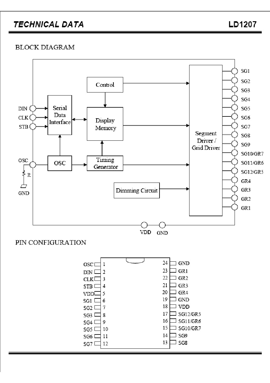
PIN DESCRIPTION
Pin Name
OSC
DIN
CLK
STB
VDD
SG1 to SG9
SG10/GR7 to
SG12/GR5
GND
GR4 to GR1
I/O
I
I
I
I
-
O
O
-
O
Description
Pin No.
Oscillator Input Pin.
A resistor is connected to this pin and GND.
1
Data Input Pin.
This pin inputs serial data at the rising edge of
the shift clock (staring from the lower bit)
2
Clock Input Pin.
Rising edge trigger.
3
Strobe pin for Serial Interface.
The data input after the STB has fallen is
processed as a command.
When this pin is "HIGH", CLK is ignored.
4
Power Supply
5,18
Segment Output Pins(p-channel, open drain)
6~14
Segment Output Pin/ Grid Output Pin
(CMOS Output)
15~17
Ground Pin
19,24
Grid Output Pins (n-channel, open drain)
20~23

4
TECHNICAL DATA
LD1207
FUNCTIONAL DESCRIPTION
Commands
A command is the first byte (b0 to b7) inputted to LD1207 via DIN Pin after STB Pin has changed from
"HIGH" to "LOW" state. If for some reason the STB Pin is set "HIGH" while data or commands are
being transmitted, the serial communication is initialized, and the data/commands being transmitted are
considered invalid.
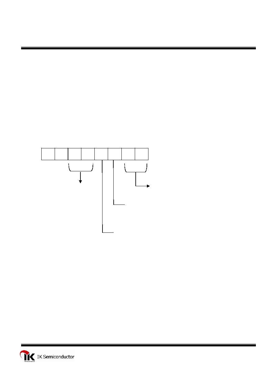
COMMAND 1 : DISPLAYMODE SETTING COMMANDS
LD1207 provides 4 display mode setting as shown in the diagram below: As stated earlier a
command is the first one byte(b0 to b7) transmitted to LD1207 via the DIN Pin when STB is
"LOW". However, for these commands, Bit No.3 to Bit No.6(b2 to b5) are ignored,
Bit No.7 & Bit No.8(b6 to b7) are given a value of "0".
The Display Mode Setting Commands determine the number of segments and grids be used
(1/4 to 1/7 duty, 12 to 9 segments). When these commands are executed, the display forcibly
turned off. A display command "ON" must be executed in order to resume display. If the same
mode setting is selected, no command execution is take place, therefore, nothing happens.
When Power is turned "ON", the 7-Grid, 9-Segment Mode is selected.
LSB
MSB
0
-
-
-
-
b1
b0
0
Display Mode Settings :
00 : 4 Grids, 12 Segments
01 : 5 Grids, 11 Segments
10 : 6 Grids, 10 Segments
11 : 7 Grids, 9 Segments
Don't Care
5
TECHNICAL DATA
LD1207
COMMAND 2 : DATA SETTING COMMANDS
The Data Setting Commands executes the Data Write Mode for LD1207. The Data Setting
Command, the bits5 and 6 (b4, b5) are ignored, bit7(b6) is given the value of "1" while bit8(b7) is
given the value of "0". Please refer to the diagram below.
When power is turned ON, bit 4 to bit 1 (b3 to b0) are given the value of "0".
LSB
MSB
0
1
-
-
b3
b2
b1
b0
Data Write Mode Settings :
00 : Write Data to Display Mode
Don't Care
Address Increment Mode Settings (Display Mode):
0 : Increment Address after Data has been Written
1 : Fixes Address
Mode Settings :
0 : Normal Operation Mode
1 : Test Mode