
Film Capacitors
EMI Suppression Capacitors (MKT)
Series/Type:
B81141
Date:
August 2004
® EPCOS AG 2004. Reproduction, publication and dissemination of this data sheet, enclosures hereto and the
information contained therein without EPCOS' prior express consent is prohibited.
Purchase orders are subject to the General Conditions for the Supply of Products and Services of the Electrical
and Electronics Industry recommended by the ZVEI (German Electrical and Electronic Manufacturers' Associ-
ation), unless otherwise agreed.

Typical applications
X1 class for interference suppression
"Across the line" applications
Climatic
Max. operating temperature: 85
░
C
Climatic category (IEC 60068-1): 40/085/21
Construction
Dielectric: polyester (MKT)
Internal series connection
Plastic case (UL 94 V-0)
Epoxy resin sealing (UL 94 V-0)
Features
Self-healing properties
Terminals
Parallel wire leads, lead-free tinned
Standard lead lengths: 6
1 mm
Special lead lengths available on request
Marking
Manufacturer's logo, lot number,
date code, rated capacitance (coded),
cap. tolerance (code letter),
rated AC voltage,
series number, sub-class (X1),
dielectric code (MKT), climatic category,
passive flammability category, approvals.
Delivery mode
Bulk (untaped)
Taped (Ammo pack or reel)
For taping details, refer to chapter
"Taping and packing".
Dimensional drawing
Dimensions in mm
Lead spacing
▒
0.4
Lead diameter
d
1
15 ... 27.5 mm
0.8
Marking example
Approvals
Marks of conformity
Standards
Certificate
EN 132400, IEC 60384-14
138583
UL 1414
E97863
CSA C22.2 No.1
E97863
EMI suppression capacitors (MKT)
B81141
X1 / 440 VAC
2
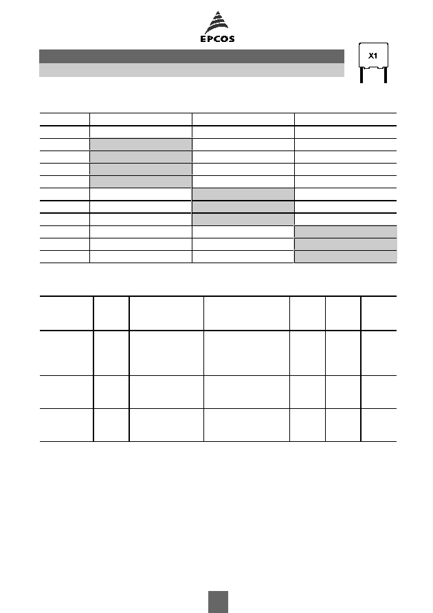
Overview of available types
Lead spacing 15 mm
22.5 mm
27.5 mm
C
R
(
Á
F)
0.010
0.022
0.033
0.047
0.068
0.10
0.15
0.22
0.33
0.47
Ordering codes and packing units
Lead spacing
mm
C
R
Á
F
Max. dimensions
w
Î
h
Î
l
mm
Ordering code
(composition see
below)
Ammo
pack
pcs./unit
Reel
pcs./unit
Untaped
pcs./unit
Further E series and intermediate capacitance values on request.
Composition of ordering code
+ =
Capacitance tolerance code:
*** = Packaging code:
M =
▒
20%
K =
▒
10%
289 = Ammo pack
189 = Reel
000 = Untaped (lead length 6
1 mm)
(Closer tolerances on request)
15
0.010
5.0
Î
10.5
Î
18.0
B81141C1103M***
1170
1300
1000
0.022
7.0
Î
12.5
Î
18.0
B81141C1223M***
830
900
1000
0.033
8.5
Î
14.5
Î
18.0
B81141C1333M***
680
700
500
0.047
9.0
Î
17.5
Î
18.0
B81141C1473M***
640
700
500
22.5
0.068
8.5
Î
16.5
Î
26.5
B81141C1683+***
480
500
510
0.10
10.5
Î
16.5
Î
26.5
B81141C1104+***
390
400
540
0.15
11.0
Î
20.5
Î
26.5
B81141C1154+***
370
350
510
27.5
0.22
12.5
Î
21.5
Î
31.5
B81141C1224+***
300
280
0.33
14.0
Î
24.5
Î
31.5
B81141C1334+***
260
0.47
18.0
Î
27.5
Î
31.5
B81141C1474+***
200
B81141
X1 / 440 VAC
3
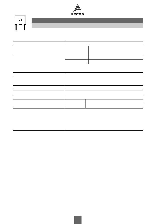
Technical data
Max. operating temperature T
op,max
+85
░
C
Dissipation factor tan
(in 10
-3
)
at
1 kHz
8.0
at 20
░
C (upper limit values)
100 kHz 15.0
Insulation resistance R
ins
C
R
0.33
Á
F
C
R
> 0.33
Á
F
or time constant
= C
R
R
ins
30 000 M
10 000 s
at 20
░
C, rel. humidity
65%
(minimum as-delivered values)
DC test voltage
2500 V, 2 s
Passive flammability category
to IEC 40 (CO) 752
C
Maximum continuous AC voltage (V
AC
) 440 V (50/60 Hz)
Rated AC voltage (IEC 60384-14)
440 V (50/60 Hz)
Maximum continuous DC voltage (V
DC
) 1000 V
Operating AC voltage V
op
at high
temperature
T
A
85
░
C
V
op
= V
AC
(continuously)
T
A
85
░
C
V
op
= 1.25
V
AC
(1000 h)
Damp heat test
21 days / 40
░
C / 93% relative humidity
Limit values after damp heat test
Capacitance change
C/C
5%
Dissipation factor change (
tan
)
5
10
-3
(at 1 kHz)
Insulation resistance R
ins
50% of minimum
or time constant
= C
R
R
ins
as-delivered values
B81141
X1 / 440 VAC
4

Pulse handling capability
"dV/dt" represents the maximum permissible voltage change per unit of time for non-sinusoidal
voltages, expressed in V/
Á
s.
"k
0
" represents the maximum permissible pulse characteristic of the waveform applied to the
capacitor, expressed in V
2
/
Á
s.
Note:
The values of dV/dt and k
0
provided below must not be exceeded in order to avoid damaging the
capacitor.
dV/dt and k
0
values
Lead spacing
15 mm
22.5 mm
27.5 mm
dV/dt in V/
Á
s
400
200
150
k
0
in V
2
/
Á
s
500 000
250 000
187 500
Impedance Z versus frequency f
(typical values)
B81141
X1 / 440 VAC
5