Microwave Ceramics and Modules
Filter
2 ≠ Pole Filter for W - LAN
B69812N2457B111
Preliminary Data Sheet
ISSUE DATE
20.05.03
ISSUE
P1
PUBLISHER
SAW MWC PD
PAGE
1/4
Features
∑
Low Profile (maximum height 1.2 mm)
∑
SMD filter consisting of coupled resonators with stepped impedances
∑
Low losses
∑
High attenuations at GSM (900, 1800, 1900) and UMTS bands
∑
High attenuation at 2 times center frequency
∑
Excellent reflow solderability, no migration effect due to copper/tin metallization
Index
Page 2
∑
Dimension Limits , Marking
∑
Recommended footprint
Page 3
∑
Characteristics
∑
Maximum ratings
∑
Typical passband characteristic
Page 4
∑
Processing information
∑
Soldering requirements
∑
Delivery mode
Microwave Ceramics and Modules
Filter
2 ≠ Pole Filter for W - LAN
B69812N2457B111
Preliminary Data Sheet
ISSUE DATE
20.05.03
ISSUE
P1
PUBLISHER
SAW MWC PD
PAGE
2/4
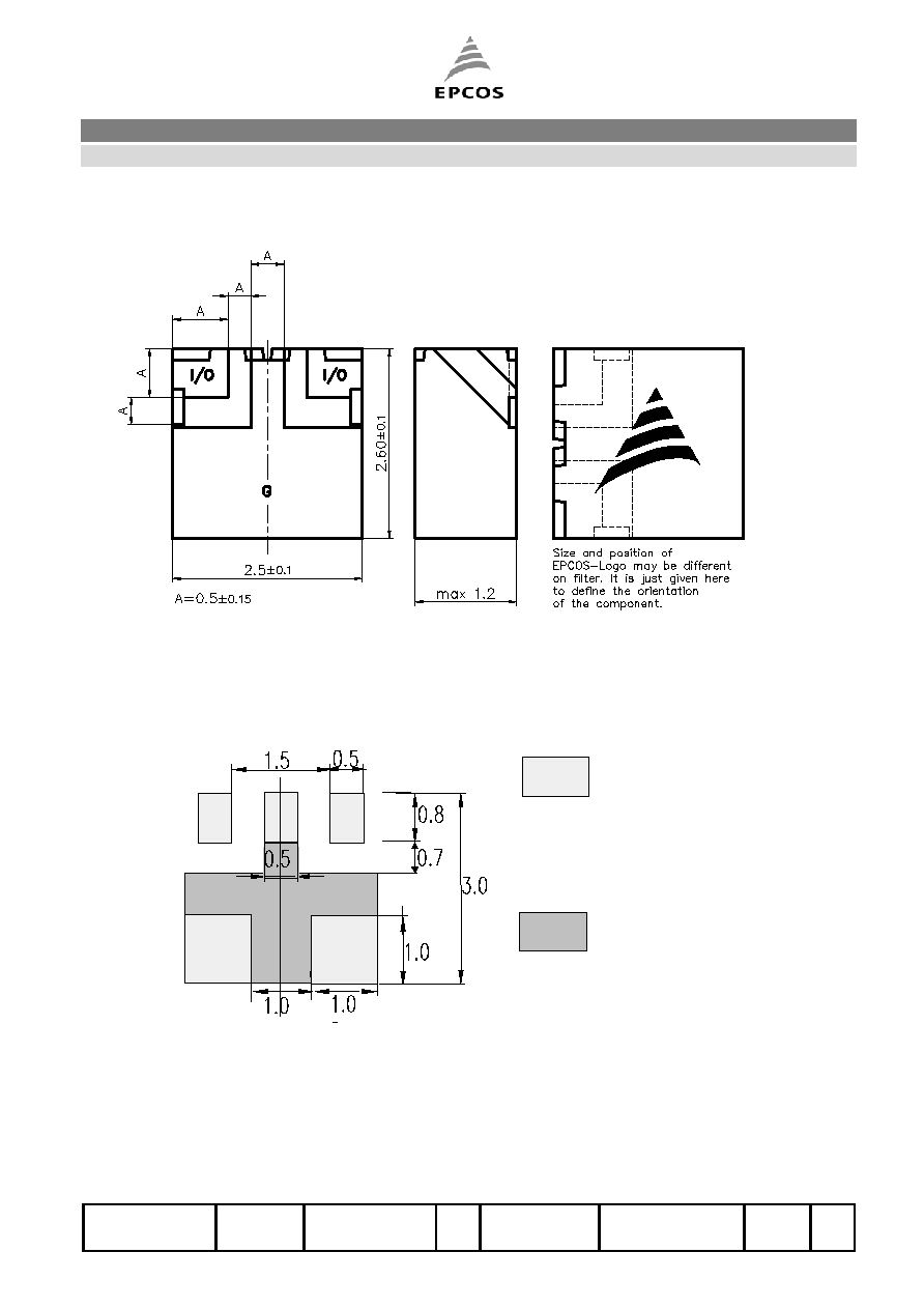
Dimension Limits , Marking
Recommended footprint (Same Footprint as for ,,X"101 and ,,X"201 WLan-Series )
Solder Pads:
I/O Pads must be
connected to lines with
50
impedance.
In the application a
termination of 50
must be realized.
Ground, covered with
solder resist, connected
to lower ground plane
by vias with maximum
diameter of 0.3mm and
max. distance of 1mm
I/O
I/O
G
G
G
View from below onto the solder terminals and view from beside
Microwave Ceramics and Modules
Filter
2 ≠ Pole Filter for W - LAN
B69812N2457B111
Preliminary Data Sheet
ISSUE DATE
20.05.03
ISSUE
P1
PUBLISHER
SAW MWC PD
PAGE
3/4
Characteristics (over whole temperature range)
min.
typ.
max.
Center frequency
fc -
2.450
-
GHz
Insertion loss in Passband
IL
2.2
2.5
dB
Passband (2400- 2500)
B 100
MHz
Amplitude ripple (peak - peak)
0.5
0.8
dB
Return Loss in dB / Standing wave ratio
-11 / 1.8
-9.5 / 2.0
Impedance
Z
50
Attenuation
RF input power
at DC to 1580 MHz
at 1805 to 1990 MHz
at 2110 to 2170 MHz
at 3200 to 4600 MHz
at 4800 to 5000 MHz
(2400 ≠ 2500 MHz)
40
38
35
20
25
43
41
37
25
30
30
dB
dB
dB
dB
dB
dBm
Maximum ratings
IEC climatic category (IEC 68-1)
- 40 /+ 90/56
Operating temperature
Top - 40 / + 85
įC
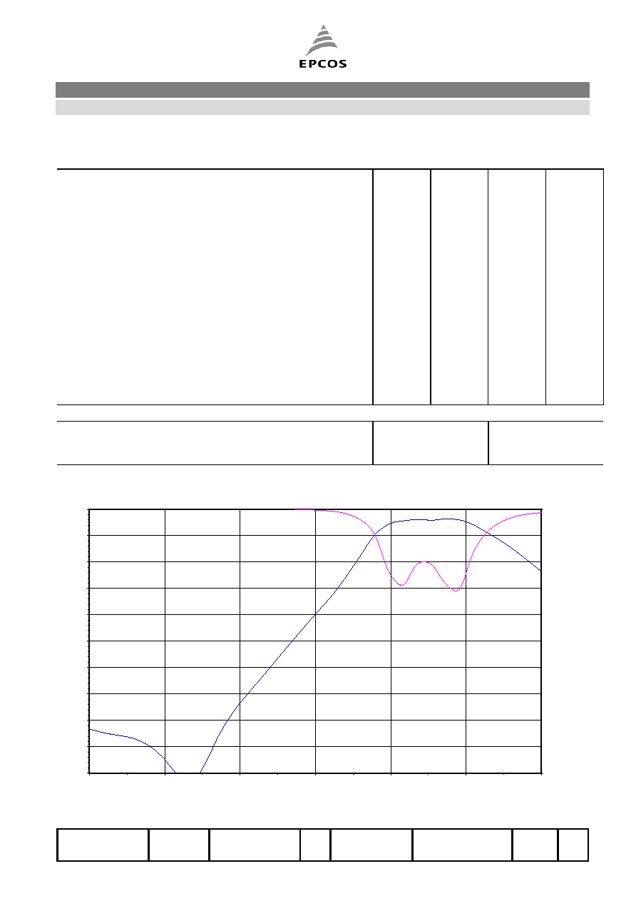
Typical passband characteristics
-50
-45
-40
-35
-30
-25
-20
-15
-10
-5
0
2.00
2.10
2.20
2.30
2.40
2.50
2.60
F [GHz]
S21 [
d
B]
Microwave Ceramics and Modules
Filter
2 ≠ Pole Filter for W - LAN
B69812N2457B111
Preliminary Data Sheet
ISSUE DATE
20.05.03
ISSUE
P1
PUBLISHER
SAW MWC PD
PAGE
4/4
Processing information
Wettability acc. to IEC 68-2-58:
75% (after aging)
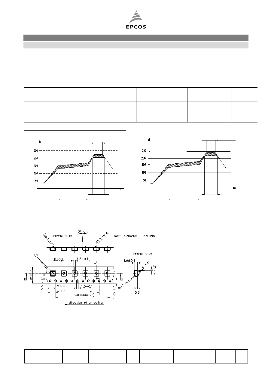
Soldering Requirements
Profile for eutectic
SnPb solder paste
Profile for leadfree
solder paste
Soldering type
reflow
reflow
Maximum soldering temperature
235 (max. 2 sec.)
260 (max. 2 sec.)
įC
(measuring point on top surface of the component) 225 (max. 10 sec.)
250 (max. 10 sec.) įC
Recommended soldering conditions (infrared):
20-40 sec.
40-80 sec.
within 10 sec.
Time [sec.]
Temp. [įC]
215įCĪ10įC
30 sec.
2-3 min.
within 10 sec.
Time [sec.]
Temp. [įC]
245įCĪ5įC
2.5 įC/s
> - 5 įC/s
Delivery mode
∑
Blister tape acc. to IEC 286-3, grey
∑
Pieces/tape: 4000
EPCOS AG 2001. All Rights Reserved. Reproduction, publication and dissemination of this data sheet, enclosures hereto and the
information contained therein without EPCOS' prior express consent is prohibited.
The information contained in this data sheet describes the type of component and shall not be considered as guaranteed characteristics.
Purchase orders are subject to the General Conditions for the Supply of Products and Services of the Electrical and Electronics Industry
recommended by the ZVEI (German Electrical and Electronic Manufacturers' Association), unless otherwise agreed.