ChipFind - Datasheet

Part Number TGL41-xx

Download:  PDF   ZIP
1
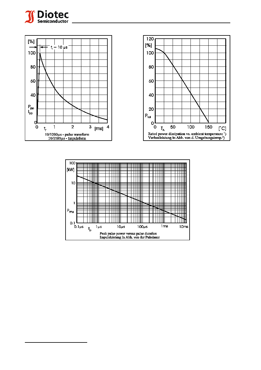
) Non-repetitive current pulse see curve I
PPM
= f (t
r
)
Höchstzulässiger Spitzenwert eines einmaligen Strom-Impulses, siehe Kurve I
PPM
= f (t
r
)
2
) Mounted on P.C. board with 25 mm
2
copper pads at each terminal
Montage auf Leiterplatte mit 25 mm
2
Kupferbelag (Lötpad) an jedem Anschluß
3
) Unidirectional diodes only ­ nur für unidirektionale Dioden
1
07.01.2003
TGL 41-6.8 ... TGL 41-200CA
Surface Mount
Unidirektionale und bidirektionale
unidirectional and bidirectional
Spannungs-Begrenzer-Dioden
Transient Voltage Suppressor Diodes
für die Oberflächenmontage
Pulse power dissipation ­ Impuls-Verlustleistung
400 W
Nominal breakdown voltage
6.8...200 V
Nominale Abbruch-Spannung
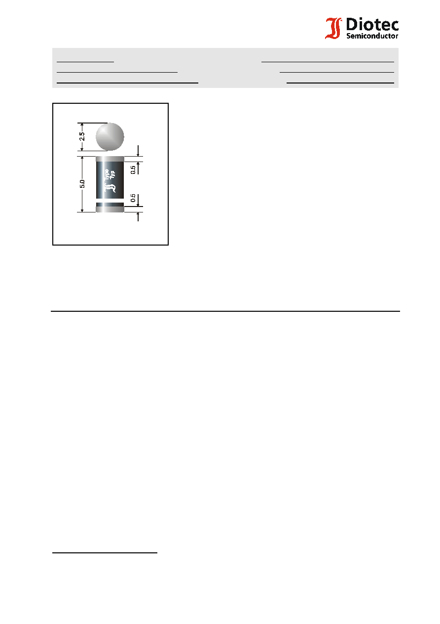
Plastic case MELF
DO-213AB
Kunststoffgehäuse MELF
Weight approx. ­ Gewicht ca.
0.12 g
Plastic material has UL classification 94V-0
Gehäusematerial UL94V-0 klassifiziert
Dimensions / Maße in mm
Standard packaging taped and reeled
see page 18
Standard Lieferform gegurtet auf Rolle
siehe Seite 18
Suffix "C" or "CA" for bidirectional types
Suffix "C" oder "CA" für bidirektionale Typen
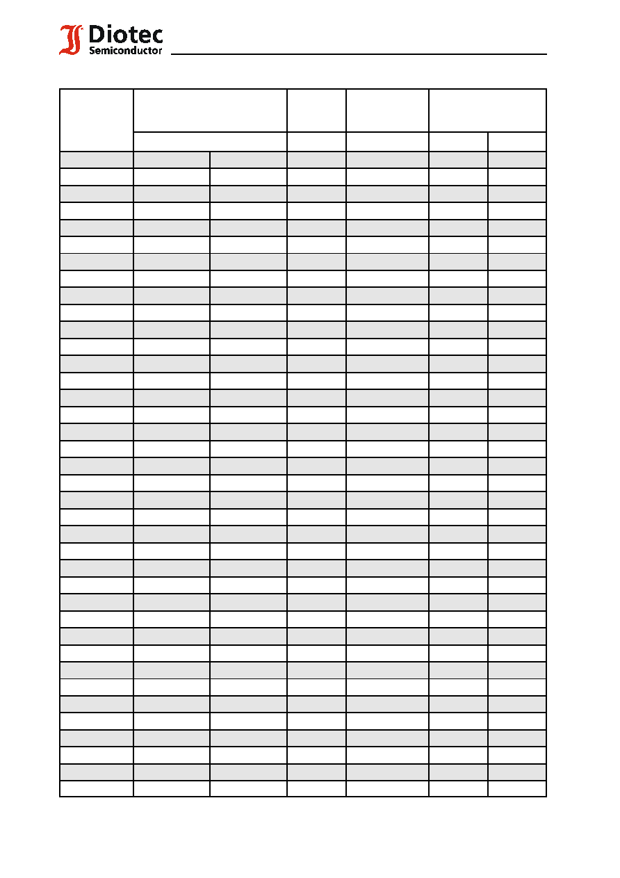
Maximum ratings and Characteristics
Grenz- und Kennwerte
Peak pulse power dissipation (10/1000
:
s waveform)
T
A
= 25
/
C
P
PPM
400 W
1
)
Impuls-Verlustleistung (Strom-Impuls 10/1000
:
s)
Steady state power dissipation
T
A
= 25
/
C
P
M(AV)
1 W
2
)
Verlustleistung im Dauerbetrieb
Peak forward surge current, 60 Hz half sine-wave
T
A
= 25
/
C
I
FSM
40 A
3
)
Stoßstrom für eine 60 Hz Sinus-Halbwelle
Max. instantaneous forward voltage
I
F
= 25 A
V
F
< 3.5 V
3
)
Augenblickswert der Durchlaßspannung
Operating junction temperature ­ Sperrschichttemperatur
T
j
­ 50...+150
/
C
Storage temperature ­ Lagerungstemperatur
T
S
­ 50...+150
/
C
Thermal resistance junction to ambient air
R
thA
< 45 K/W
2
)
Wärmewiderstand Sperrschicht ­ umgebende Luft
Thermal resistance junction to terminal
R
thT
< 10 K/W
Wärmewiderstand Sperrschicht ­ Kontaktfläche
2
F:\Data\Wp\DatBlatt\Einzelblätter\tgl41.wpd
TGL 41-6.8 ... TGL 41-200CA
Maximum ratings
Grenzwerte
Type
Typ
Breakdown voltage at I
T
= 1 mA
Abbruch-Spanng. bei I
T
= 1 mA
*) at / bei I
T
= 10 mA
Stand-off
voltage
Sperrspg.
Max. rev. current
Max. Sperrstrom
at / bei V
WM
Max. clamping voltage
Max. Begrenzerspanng.
at / bei I
PPM
(10/1000
:
s)
V
BR
[V]
V
WM
[V]
I
D
[
:
A]
V
C
[V]
I
PPM
[A]
TGL 41-6.8
6.8 ± 10%
6.12...7.48 *)
5.5
1000
10.8
38.0
TGL 41-6.8A
6.8 ± 5%
6.45...7.14 *)
5.8
1000
10.5
40.0
TGL 41-7.5
7.5 ± 10%
6.75...8.25 *)
6.0
500
11.7
35.0
TGL 41-7.5A
7.5 ± 5%
7.13...7.88 *)
6.4
500
11.3
37.0
TGL 41-8.2
8.2 ± 10%
7.38...9.02 *)
6.6
200
12.5
33.0
TGL 41-8.2A
8.2 ± 5%
7.79...8.61 *)
7.0
200
12.1
34.0
TGL 41-9.1
9.1 ± 10%
8.19...10.0
7.3
50
13.8
30.0
TGL 41-9.1A
9.1 ± 5%
8.65...9.55
7.7
50
13.4
31.0
TGL 41-10
10 ± 10%
9.0...11.0
8.1
10
15.0
28.0
TGL 41-10A
10 ± 5%
9.5...10.5
8.5
10
14.5
29.0
TGL 41-11
11 ± 10%
9.9...12.1
8.9
5
16.2
26.0
TGL 41-11A
11 ± 5%
10.5...11.6
9.4
5
15.6
27.0
TGL 41-12
12 ± 10%
10.8...13.2
9.7
5
17.3
24.0
TGL 41-12A
12 ± 5%
11.4...12.6
10.2
5
16.7
25.0
TGL 41-13
13 ± 10%
11.7...14.3
10.5
5
19.0
22.0
TGL 41-13A
13 ± 5%
12.4...13.7
11.1
5
18.2
23.0
TGL 41-15
15 ± 10%
13.5...16.5
12.1
5
22.0
19.0
TGL 41-15A
15 ± 5%
14.3...15.8
12.8
5
21.2
21.0
TGL 41-16
16 ± 10%
14.4...17.6
12.9
5
23.5
17.8
TGL 41-16A
16 ± 5%
15.2...16.8
13.6
5
22.5
18.6
TGL 41-18
18 ± 10%
16.2...19.8
14.5
5
26.5
16.0
TGL 41-18A
18 ± 5%
17.1...18.9
15.3
5
25.5
16.5
TGL 41-20
20 ± 10%
18.0...22.0
16.2
5
29.1
14.0
TGL 41-20A
20 ± 5%
19.0...21.0
17.1
5
27.7
15.0
TGL 41-22
22 ± 10%
19.8...24.2
17.8
5
31.9
13.0
TGL 41-22A
22 ± 5%
20.9...23.1
18.8
5
30.6
13.7
TGL 41-24
24 ± 10%
21.6...26.4
19.4
5
34.7
12.0
TGL 41-24A
24 ± 5%
22.8...25.2
20.5
5
33.2
12.6
TGL 41-27
27 ± 10%
24.3...29.7
21.8
5
39.1
10.7
TGL 41-27A
27 ± 5%
25.7...28.4
23.1
5
37.5
11.0
TGL 41-30
30 ± 10%
27.0...33.0
24.3
5
43.5
9.6
TGL 41-30A
30 ± 5%
28.5...31.5
25.6
5
41.4
10.0
TGL 41-33
33 ± 10%
29.7...36.3
26.8
5
47.7
8.8
TGL 41-33A
33 ± 5%
31.4...34.7
28.2
5
45.7
9.0
TGL 41-36
36 ± 10%
32.4...39.6
29.1
5
52.0
8.0
TGL 41-36A
36 ± 5%
34.2...37.8
30.8
5
49.9
8.4
TGL 41-39
39 ± 10%
35.1...42.9
31.6
5
56.4
7.4
TGL 41-39A
39 ± 5%
37.1...41.0
33.3
5
53.9
7.7
For bidirectional types (suffix "C" or "CA") electrical characteristics apply in both directions
3
07.01.2003
TGL 41-6.8 ... TGL 41-200CA
Maximum ratings
Grenzwerte
Type
Typ
Breakdown voltage at I
T
= 1 mA
Abbruch-Spanng. bei I
T
= 1 mA
*) at / bei I
T
= 10 mA
Stand-off
voltage
Sperrspg.
Max. rev. current
Max. Sperrstrom
at / bei V
WM
Max. clamping voltage
Max. Begrenzerspanng.
at / bei I
PPM
(10/1000
:
s)
V
BR
[V]
V
WM
[V]
I
D
[
:
A]
V
C
[V]
I
PPM
[A]
TGL 41-43
43 ± 10%
38.7...47.3
34.8
5
61.9
6.7
TGL 41-43A
43 ± 5%
40.9...45.2
36.8
5
59.3
7.0
TGL 41-47
47 ± 10%
42.3...51.7
38.1
5
67.8
6.2
TGL 41-47A
47 ± 5%
44.7...49.4
40.2
5
64.8
6.4
TGL 41-51
51 ± 10%
45.9...56.1
41.3
5
73.5
5.7
TGL 41-51A
51 ± 5%
48.5...53.6
43.6
5
70.1
6.0
TGL 41-56
56 ± 10%
50.4...61.6
45.4
5
80.5
5.2
TGL 41-56A
56 ± 5%
53.2...58.8
47.8
5
77.0
5.4
TGL 41-62
62 ± 10%
55.8...68.8
50.2
5
89.0
4.7
TGL 41-62A
62 ± 5%
58.9...65.1
53.0
5
85.0
5.0
TGL 41-68
68 ± 10%
61.2...74.8
55.1
5
98.0
4.2
TGL 41-68A
68 ± 5%
64.6...71.4
58.1
5
92.0
4.5
TGL 41-75
75 ± 10%
67.5...82.5
60.7
5
108
3.8
TGL 41-75A
75 ± 5%
71.3...78.8
64.1
5
103
4.0
TGL 41-82
82 ± 10%
73.8...90.2
66.4
5
118
3.5
TGL 41-82A
82 ± 5%
77.9...86.1
70.1
5
113
3.7
TGL 41-91
91 ± 10%
81.9...100
73.7
5
131
3.2
TGL 41-91A
91 ± 5%
86.5...95.5
77.8
5
125
3.3
TGL 41-100
100 ± 10%
90.0...110
81.0
5
144
2.9
TGL 41-100A
100 ± 5%
95.0...105
85.5
5
137
3.0
TGL 41-110
110 ± 10%
99.0...121
89.2
5
158
2.6
TGL 41-110A
110 ± 5%
105...116
94.0
5
152
2.7
TGL 41-120
120 ± 10%
108...132
97.2
5
173
2.4
TGL 41-120A
120 ± 5%
114...126
102
5
165
2.5
TGL 41-130
130 ± 10%
117...143
105
5
187
2.2
TGL 41-130A
130 ± 5%
124...137
111
5
179
2.3
TGL 41-150
150 ± 10%
135...165
121
5
215
1.9
TGL 41-150A
150 ± 5%
143...158
128
5
207
2.0
TGL 41-160
160 ± 10%
144...176
130
5
230
1.8
TGL 41-160A
160 ± 5%
152...168
136
5
219
1.9
TGL 41-170
170 ± 10%
153...187
138
5
244
1.7
TGL 41-170A
170 ± 5%
162...179
145
5
234
1.8
TGL 41-180
180 ± 10%
162...198
146
5
258
1.6
TGL 41-180A
180 ± 5%
171...189
154
5
246
1.7
TGL 41-200
200 ± 10%
180...220
162
5
287
1.4
TGL 41-200A
200 ± 5%
190...210
171
5
274
1.5
For bidirectional types (suffix "C" or "CA") electrical characteristics apply in both directions
Für bidirektionale Dioden (Suffix "C" oder "CA") gelten die el. Werte in beiden Richtungen
1
) Mounted on P.C. board with 25 mm
2
copper pads at each terminal
Montage auf Leiterplatte mit 25 mm
2
Kupferbelag (Lötpad) an jedem Anschluß
4
F:\Data\Wp\DatBlatt\Einzelblätter\tgl41.wpd
TGL 41-6.8 ... TGL 41-200CA
1
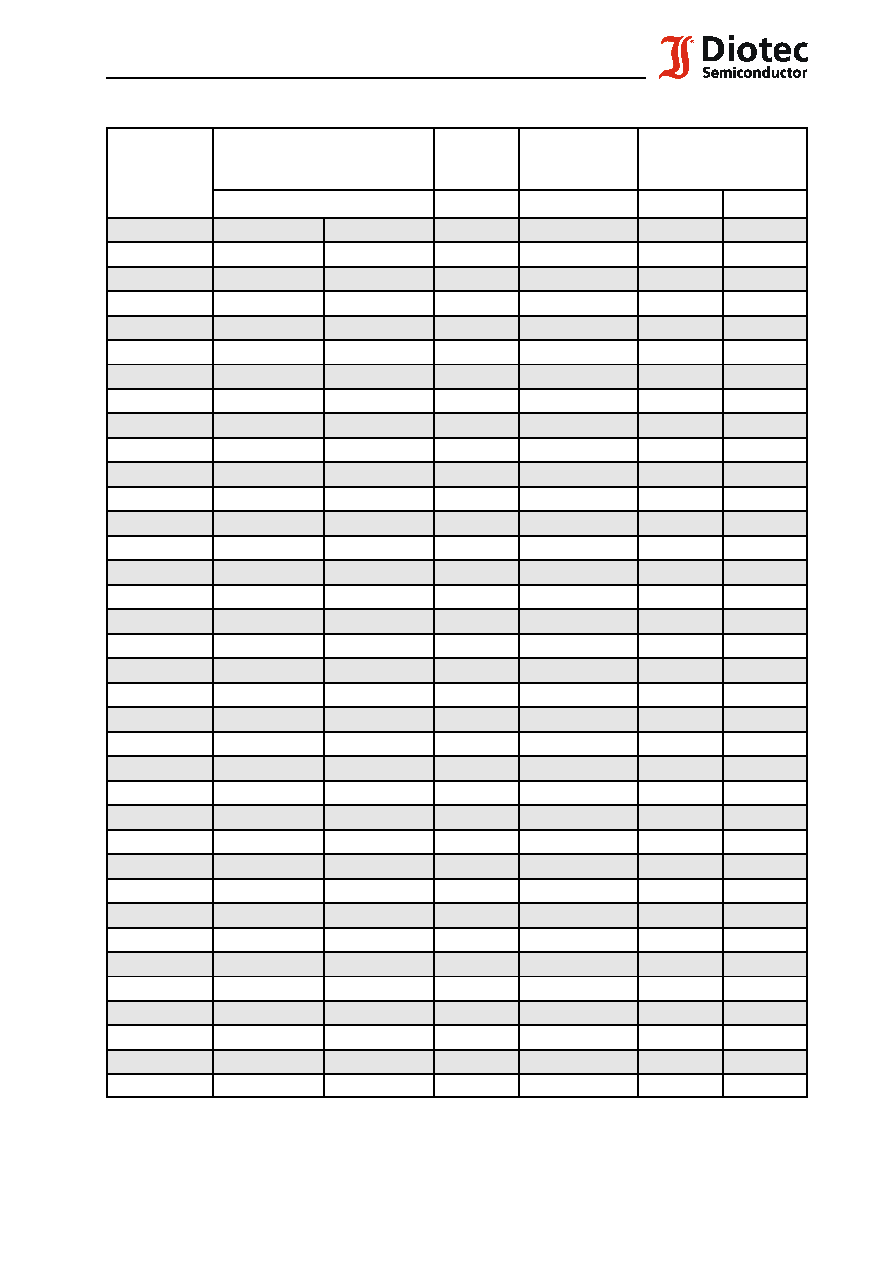
The order of type numbers is graded to the international E 24 standard. The standard tolerance of
the breakdown voltage for each type is ± 10%. Suffix "A" denotes a tolerance of ± 5% for the
breakdown voltage.
e.g.: TGL 41-51C = bidirectional diode, V
BR
= 51 V (± 10%), V
WM
$
41.3 V at I
D
= 5
:
A
TGL 41-9.1A = unidirectional diode, V
BR
= 9.1 V (± 5%), V
WM
$
7.7 V at I
D
= 50
:
A
Die Abstufung der Typen innerhalb der Reihe entspricht dem internationalen E 24-Standard. Die
Toleranz der Arbeitsspannung jedes einzelnen Typs beträgt in der Standardausführung ± 10%.
Suffix "A" kennzeichnet eine Toleranz der Arbeitsspannung von ± 5%.
z.B.: TGL 41-51C = bidirectionale Diode, V
BR
= 51 V (± 10%), V
WM
$
41.3 V at I
D
= 5
:
A
TGL 41-9.1A = unidirectionale Diode, V
BR
= 9.1 V (± 5%), V
WM
$
7.7 V at I
D
= 50
:
A