1
) I
F
= 1 A, T
A
= 25
/
C
2
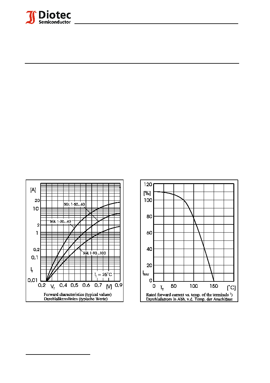
) Max. temperature of the terminals T
T
= 100
/
C Max. Temperatur der Anschlüsse T
T
= 100
/
C
1
30.06.2002
3.
5
1.
6
0.
4
0.
4
SGL 1-20 ... SGL 1-100
Schottky-Gleichrichter
Surface Mount Schottky-Rectifiers
für die Oberflächenmontage
Nominal current Nennstrom
1 A
Repetitive peak reverse voltage
20...100 V
Periodische Spitzensperrspannung
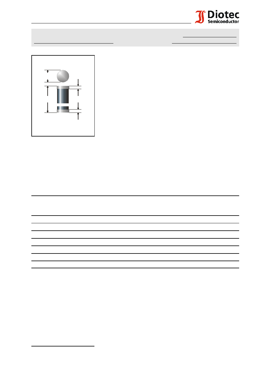
Plastic case MiniMELF
SOD 80
Kunststoffgehäuse MiniMELF
DO-213AA
Weight approx. Gewicht ca.
0.04 g
Plastic material has UL classification 94V-0
Gehäusematerial UL94V-0 klassifiziert
Dimensions / Maße in mm
Standard packaging taped and reeled
see page 18
Standard Lieferform gegurtet auf Rolle
siehe Seite 18
Marking:
One gray ring denotes "cathode" and "Schottky-Rectifier"
The type numbers are noted only on the lable on the reel
Kennzeichnung: Ein grauer Ring kennzeichnet "Kathode" und "Schottky-Gleichrichter"
Die Typenbezeichnungen sind nur auf dem Rollenaufkleber vermerkt
Maximum ratings
Grenzwerte
Type
Typ
Repetitive peak reverse voltage
Periodische Spitzensperrspannung
V
RRM
[V]
Surge peak reverse voltage
Stoßspitzensperrspannung
V
RSM
[V]
Forward voltage
Durchlaßspannung
V
F
[V]
1
)
SGL 1-20
20
20
< 0.50
SGL 1-30
30
30
< 0.50
SGL 1-40
40
40
< 0.50
SGL 1-50
50
50
< 0.67
SGL 1-60
60
60
< 0.67
SGL 1-90
90
90
< 0.82
SGL 1-100
100
100
< 0.82
Max. average forward rectified current, R-load
T
T
= 75
/
C
I
FAV
1 A
Dauergrenzstrom in Einwegschaltung mit R-Last
Repetitive peak forward current
f > 15 Hz
I
FRM
10 A
2
)
Periodischer Spitzenstrom
Peak forward surge current, 50 Hz half sine-wave
T
A
= 25
/
C
I
FSM
20 A
Stoßstrom für eine 50 Hz Sinus-Halbwelle
1
) Mounted on P.C. board with 25 mm
2
copper pads at each terminal
Montage auf Leiterplatte mit 25 mm
2
Kupferbelag (Lötpad) an jedem Anschluß
2
F:\Data\WP\DatBlatt\Einzelblätter\sgl1.wpd
SGL 1-20 ... SGL 1-100
Operating junction temperature Sperrschichttemperatur
T
j
50...+150
/
C
Storage temperature Lagerungstemperatur
T
S
50...+150
/
C
Characteristics
Kennwerte
Leakage current Sperrstrom
T
j
= 25
/
C
V
R
= V
RRM
I
R
< 0.5 mA
T
j
= 100
/
C
V
R
= V
RRM
I
R
< 5.0 mA
Junction capacitance
V
R
= 6 V
f = 1 MHz
C
j
40 pF
Sperrschichtkapazität
Thermal resistance junction to ambient air
R
thA
< 150 K/W
1
)
Wärmewiderstand Sperrschicht umgebende Luft
Thermal resistance junction to terminal
R
thT
< 60 K/W
Wärmewiderstand Sperrschicht Anschluß