1
) Valid for one branch Gültig für einen Brückenzweig
1
01.07.03
GBI 15A ... GBI 15M
Silicon-Bridge Rectifiers
Silizium-Brückengleichrichter
Nominal current Nennstrom
15 A
Repetitive peak reverse voltage
50...1000 V
Periodische Spitzensperrspannung
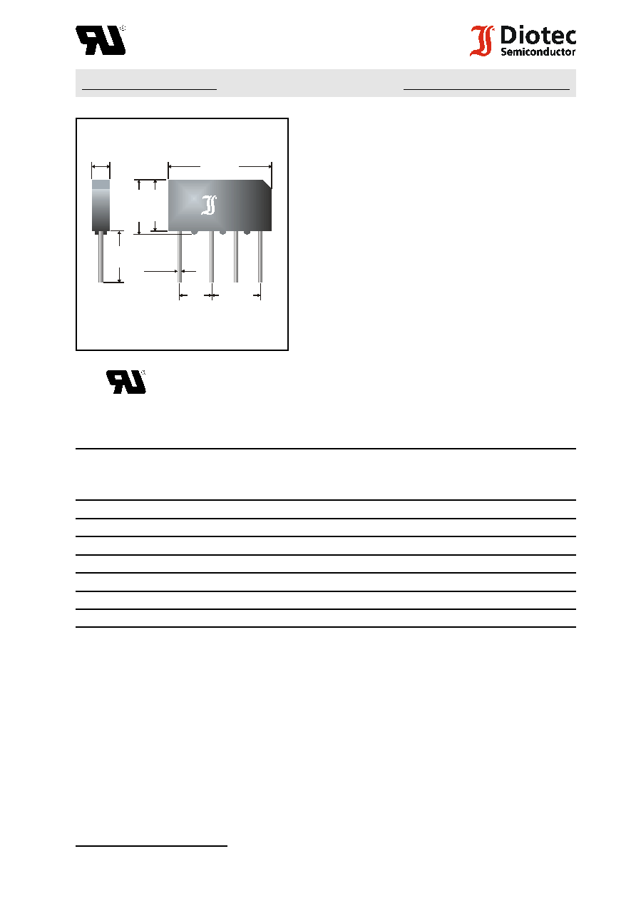
Plastic case
32 x 5.6 x 17 [mm]
Kunststoffgehäuse
Weight approx. Gewicht ca.
9 g
Plastic material has UL classification 94V-0
Gehäusematerial UL94V-0 klassifiziert
Standard packaging: bulk
see page 22
Standard Lieferform: lose im Karton
s. Seite 22
Dimensions / Maße in mm
Mounting clamp BO 2
see page 28
Befestigungsschelle BO 2
see page 28
Recognized Product Underwriters Laboratories Inc.® File E175067
Anerkanntes Produkt Underwriters Laboratories Inc.® Nr. E175067
Maximum ratings
Grenzwerte
Type
Typ
max. alternating input voltage
max. Eingangswechselspannung
V
VRMS
[V]
Repetitive peak reverse voltage
Periodische Spitzensperrspannung
V
RRM
[V]
1
)
GBI 15A
35
50
GBI 15B
70
100
GBI 15D
140
200
GBI 15G
280
400
GBI 15J
420
600
GBI 15K
560
800
GBI 15M
700
1000
Peak forward surge current, 50 Hz half sine-wave
T
A
= 25
/
C
I
FSM
220 A
Stoßstrom für eine 50 Hz Sinus-Halbwelle
Peak forward surge current, 60 Hz half sine-wave
T
A
= 25
/
C
I
FSM
240 A
Stoßstrom für eine 60 Hz Sinus-Halbwelle
Rating for fusing, t < 10 ms
T
A
= 25
/
C
i
2
t
240 A
2
s
Grenzlastintegral, t < 10 ms
Operating junction temperature Sperrschichttemperatur
T
j
50...+150
/
C
Storage temperature Lagerungstemperatur
T
S
50...+150
/
C
5.6
±0.2
32
±0.2
16
±0
.
2
17
±0
.
2
10
2x7.5
Ř
1.2
Type
Typ
16
~
+
~
1
) Valid for one branch Gültig für einen Brückenzweig
2
) Without cooling fin Ohne Kühlblech
3
) Mounted on heatsink with silicon thermal compound and forced airflow resp water cooling
Montage auf Kühlkörper mit Wärmeleitpaste und Gebläse- bzw. Wasserkühlung
2
F:\Data\WP\DatBlatt\Einzelblätter\gbi15a-15m.wpd
GBI 15A ... GBI 15M
Characteristics
Kennwerte
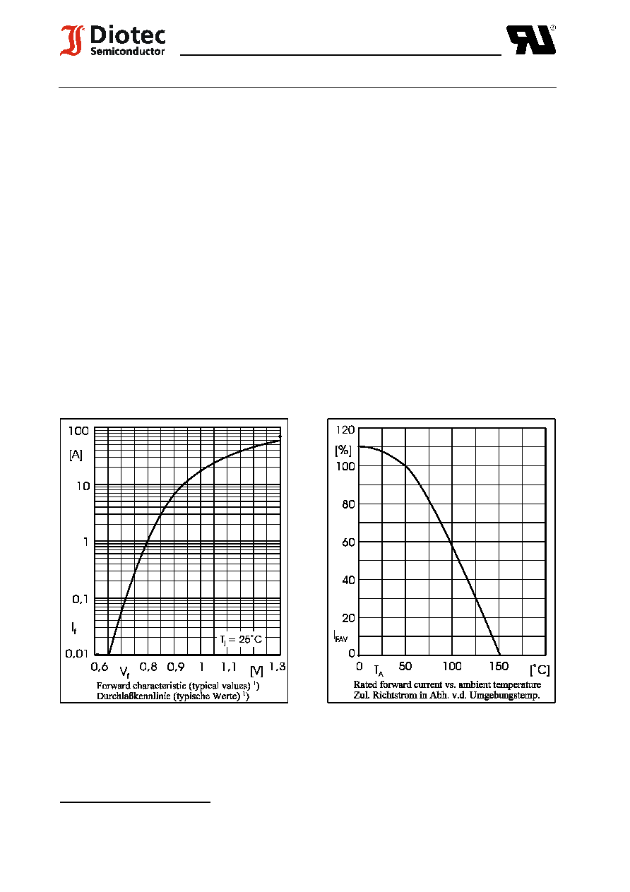
Max. fwd. current without cooling fin
T
A
= 50
/
C
R-load
I
FAV
3.5 A
Dauergrenzstrom ohne Kühlblech
C-load
I
FAV
2.8 A
Max. current with forced cooling
T
C
= 100
/
C
R-load
I
FAV
15 A
3
)
Dauergrenzstrom mit forcierter Kühlung
C-load
I
FAV
12 A
3
)
Forward voltage Durchlaßspannung
T
j
= 25
/
C
I
F
= 7.5 A
V
F
< 1.05 V
1
)
Leakage current Sperrstrom
T
j
= 25
/
C
V
R
= V
RRM
I
R
< 10
:
A
Typical thermal resistance junction to ambient air
R
thA
20 K/W
2
)
Typischer Wärmewiderstand Sperrschicht umgebende Luft
Typical thermal resistance junction to case
R
thC
2.5 K/W
3
)
Typischer Wärmewiderstand Sperrschicht Gehäuse