1
) Valid, if leads are kept at ambient temperature at a distance of 2 mm from case
GŘltig, wenn die Anschlu▀drńhte in 2 mm Abstand von Gehńuse auf Umgebungstemperatur gehalten werden
32
2N3905, 2N3906
Switching Transistors
PNP
Si-Epitaxial PlanarTransistors
PNP
Version 2004-01-20
Power dissipation ş Verlustleistung
625 mW
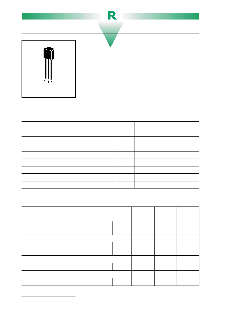
Plastic case
TO-92
Kunststoffgehńuse
(10D3)
Weight approx. ş Gewicht ca.
0.18 g
Plastic material has UL classification 94V-0
Gehńusematerial UL94V-0 klassifiziert
Standard Pinning
1 = C 2 = B 3 = E
Standard packaging taped in ammo pack
Standard Lieferform gegurtet in Ammo-Pack
Maximum ratings (T
A
= 25
/C)
Grenzwerte (T
A
= 25
/C)
2N3905, 2N3906
Collector-Emitter-voltage
B open
- V
CE0
40 V
Collector-Base-voltage
E open
- V
CE0
40 V
Emitter-Base-voltage
C open
- V
EB0
5 V
Power dissipation ş Verlustleistung
P
tot
625 mW
1
)
Collector current ş Kollektorstrom (dc)
- I
C
100 mA
Peak collector current ş Kollektorspitzenstrom
- I
CM
200 mA
Junction temp. ş Sperrschichttemperatur
T
j
150
/C
Storage temperature ş Lagerungstemperatur
T
S
- 55...+ 150
/C
Characteristics (T
j
= 25
/C)
Kennwerte (T
j
= 25
/C)
Min.
Typ.
Max.
Collector saturation volt. ş Kollektor-Sńttigungsspannung
- I
C
= 10 mA, - I
B
= 1 mA
- I
C
= 50 mA, - I
B
= 5 mA
- V
CEsat
- V
CEsat
ş
ş
ş
ş
250 mV
400 mV
Base saturation voltage ş Basis-Sńttigungsspannung
- I
C
= 10 mA, - I
B
= 1 mA
- I
C
= 50 mA, - I
B
= 5 mA
- V
BEsat
- V
BEsat
ş
ş
ş
ş
850 mV
950 mV
Collector cutoff current ş Kollektorreststrom
- V
CE
= 30 V, - V
EB
= 3 V
- I
CEV
ş
ş
50 nA
Emitter cutoff current ş Emitterreststrom
- V
CE
= 30 V, - V
EB
= 3 V
- I
EBV
ş
ş
50 nA

1
) Valid, if leads are kept at ambient temperature at a distance of 2 mm from case
GŘltig, wenn die Anschlu▀drńhte in 2 mm Abstand von Gehńuse auf Umgebungstemperatur gehalten werden
33
General Purpose Transistors
2N3905, 2N3906
Characteristics (T
j
= 25
/C)
Kennwerte (T
j
= 25
/C)
Min.
Typ.
Max.
DC current gain ş Kollektor-Basis-Stromverhńltnis
- V
CE
= 1 V, - I
C
= 0.1 mA
2N3905
2N3906
h
FE
h
FE
30
60
ş
ş
ş
ş
- V
CE
= 1 V, - I
C
= 1 mA
2N3905
2N3906
h
FE
h
FE
40
80
ş
ş
ş
ş
- V
CE
= 1 V, - I
C
= 10 mA
2N3905
2N3906
h
FE
h
FE
50
100
ş
ş
150
300
- V
CE
= 1 V, - I
C
= 50 mA
2N3905
2N3906
h
FE
h
FE
30
60
ş
ş
ş
ş
- V
CE
= 1 V, - I
C
= 100 mA
2N3905
2N3906
h
FE
h
FE
15
30
ş
ş
ş
ş
Gain-Bandwidth Product ş Transitfrequenz
- V
CE
= 20 V, - I
C
= 10 mA,
f = 100 MHz
2N3905
2N3906
f
T
f
T
200 MHz
250 MHz
ş
ş
ş
ş
Collector-Base Capacitance ş Kollektor-Basis-Kapazitńt
- V
CB
= 5 V, I
E
= i
e
= 0, f = 100 kHz
C
CB0
ş
ş
4.5 pF
Emitter-Base Capacitance ş Emitter-Basis-Kapazitńt
- V
EB
= 0.5 V, I
C
= i
c
= 0, f = 100 kHz
C
EB0
ş
ş
10 pF
Noise figure ş Rauschzahl
- V
CE
= 5 V, - I
C
= 100
:A
R
G
= 1 k
S f = 10 Hz ...15.7 kHz
2N3905
2N3906
F
F
ş
ş
ş
ş
5 dB
4 dB
Switching times ş Schaltzeiten
turn-on time
I
Con
= 10 mA,
I
Bon
= - I
Boff
= 1 mA
t
on
ş
ş
70
turn-off time
t
off
ş
ş
300
Thermal resistance junction to ambient air
Wńrmewiderstand Sperrschicht ş umgebende Luft
R
thA
200 K/W
1
)
Recommended complementary NPN transistors
Empfohlene komplementńre NPN-Transistoren
2N3903, 2N3904