
Lead-free Green
DS30589 Rev. 7 - 2
1 of 3
SDM20U30LP
www.diodes.com
ă
Diodes Incorporated
SDM20U30LP
SURFACE MOUNT SCHOTTKY BARRIER DIODE
Features
·
Low Forward Voltage Drop
·
Guard Ring Construction for
Transient Protection
·
Low Capacitance
·
Ultra-Small Surface Mount Package
·
Lead Free By Design/RoHS Compliant (Note 1)
·
"Green" Device (Note 2)
·
Qualified to AEC-Q101 Standards for High Reliability
·
Case: DFN1006-2
·
Case Material: Molded Plastic, "Green" Molding
Compound. UL Flammability Classification Rating 94V-0
·
Moisture Sensitivity: Level 1 per J-STD-020C
·
Terminal Connections: Cathode Dot
·
Terminals: Finish
ľ NiPdAu annealed over Copper
leadframe. Solderable per MIL-STD-202, Method 208
·
Marking Code: LM, Dot Denotes Cathode Side
·
Ordering Information: See Last Page
·
Weight: 0.001 grams
Mechanical Data
Maximum Ratings
@ T
A
= 25
°C unless otherwise specified
Electrical Characteristics
@ T
A
= 25
°C unless otherwise specified
Characteristic
Symbol
Value
Unit
Peak Repetitive Reverse Voltage
Working Peak Reverse Voltage
DC Blocking Voltage
V
RRM
V
RWM
V
R
30
V
RMS Reverse Voltage
V
R(RMS)
21
V
Maximum (Peak) Forward Current
I
FM
200
mA
Peak Forward Surge Current
8.3ms Half Sine
I
FSM
1.0
A
Operating and Storage Temperature Range
T
j
, T
STG
-65 to +125
°C
Characteristic
Symbol
Min
Typ
Max
Unit
Test Conditions
Reverse Breakdown Voltage (Note 3)
V
(BR)R
30
ľ
ľ
V
I
R
= 150
mA
Forward Voltage Drop
V
F
ľ
ľ
350
575
mV
I
F
= 20mA
I
F
= 200mA
Peak Reverse Current (Note 3)
I
R
ľ
ľ
150
30
mA
mA
V
R
= 30V
V
R
= 10V
Total Capacitance
C
T
ľ
20
ľ
pF
V
R
= 0V, f = 1.0MHz
NEW
P
RODUCT
Note: 1. No purposefully added lead.
2. Diodes Inc.'s "Green" policy can be found on our website at http://www.diodes.com/products/lead_free/index.php.
3. Short duration pulse test used so as to minimize self-heating effect.
Thermal Characteristics
@ T
A
= 25
°C unless otherwise specified
Characteristic
Symbol
Value
Unit
Power Dissipation
P
d
250
mW
Thermal Resistance, Junction to Ambient Air
R
qJA
400
°C/W
D
G
H
B
C
R
N
A
DFN1006-2
Dim
Min
Max
Typ
A
0.95
1.075
1.00
B
0.55
0.675
0.60
C
0.45
0.55
0.50
D
0.20
0.30
0.25
G
0.47
0.53
0.50
H
0
0.05
0.03
N
ľ
ľ
0.40
R
0.05
0.15
0.10
All Dimensions in mm
SPICE MODEL: SDM20U30LP
DS30589 Rev. 7 - 2
2 of 3
SDM20U30LP
www.diodes.com
0
50
100
0
25
50
75
100
125
P
,
POWER
D
ISSIP
A
TION
(mW)
D
T , AMBIENT TEMPERATURE (°C)
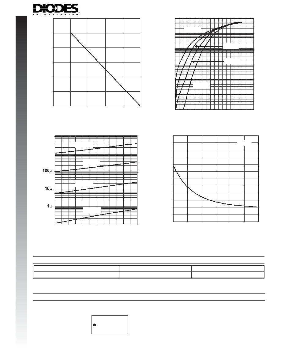
Fig. 1 Power Derating Curve
A
150
200
250
300
.001
.01
.1
1
10
1000
100
0
200
400
600
800
V , INSTANTANEOUS FORWARD VOLTAGE (mV)
Fig. 2 Typical Forward Characteristics
F
I
,
INST
ANT
A
NEOUS
FOR
W
A
RD
CURRENT
(mA)
F
T = 25°C
A
T = 75°C
A
T = 125°C
A
T = -25°C
A
NEW
P
RODUCT
0
5
10
15
20
25
30
I
,
INST
ANT
A
NEOUS
R
EVERSE
CURRENT
(A)
R
V , INSTANTANEOUS REVERSE VOLTAGE (V)
Fig. 3 Typical Reverse Characteristics
R
100n
10m
1m
T = 25°C
A
T = 75°C
A
T = 125°C
A
T = -25°C
A
Ordering Information
Device
Packaging
Shipping
SDM20U30LP-7
DFN1006-2
3000/Tape & Reel
(Note 4)
Note: 4. For Packaging Details, go to our website at http://www.diodes.com/datasheets/ap02007.pdf.
LM = Product Type Marking Code, Dot Denotes Cathode Side
LM
Marking Information
0
5
10
15
20
25
30
0
2
6
4
8
10
12
C
,
T
O
T
A
L
C
AP
ACIT
ANCE
(pF)
T
V , REVERSE VOLTAGE (V)
Fig. 4 Typical Total Capacitance
vs. Reverse Voltage
R
f = 1MHz

DS30589 Rev. 7 - 2
3 of 3
SDM20U30LP
www.diodes.com
NEW
P
RODUCT
IMPORTANT NOTICE
LIFE SUPPORT
www.diodes.com
Diodes, Inc. and its subsidiaries reserve the right to make changes without further notice to any product herein to make corrections, modifications, enhance-
ments, improvements, or other changes. Diodes, Inc. does not assume any liability arising out of the application or use of any product described herein;
neither does it convey any license under its patent rights, nor the rights of others. The user of products in such applications shall assume all risks of such
use and will agree to hold Diodes Incorporated and all the companies whose products are represented on our website, harmless against all damages.
The products located on our website at
are not recommended for use in life support systems where a failure or malfunction of the
component may directly threaten life or cause injury without the expressed written approval of Diodes Incorporated.