
4-10
Dialight Corporation · 1501 Route 34 South · Farmingdale, NJ 07727 · TEL: (732) 919-3119 · FAX: (732) 751-5778 ·www.dialight.com
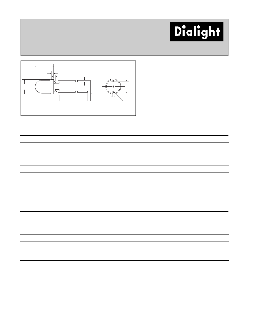
3mm
LED CBI
®
Circuit Board Indicator
(DIN 41494 Compatible)
551-xx01
5.00 [.197]
10.00 [.394]
10.00
[.394]
5.00
[.197]
2.54
[.100]
2.92
[.115]
3.35
[.132]*
6.84
[.269]
2.54
[.100]
RECOMMENDED
P.C. BOARD
LAYOUT
2.54
[.100]
1.09
[.043]
1.09
[.043]
1.27
[.050]
3.20
[.126]
* 3.56 [.140] FOR BICOLOR
ANODE
(RED/YELLOW
ANODE FOR
BICOLOR)
1.00
[.039]
1.00
[.039]
.508
[.020]
D
PART NO.
COLOR
HIGH EFFICIENCY
551-0201
Green
551-0301
Yellow
551-0401
Red
551-0801
Blue
ł
551-2501
Orange
INTEGRAL RESISTOR, 5 VOLTS
551-0501
Red
551-0601
Green
551-0701
Yellow
LOW CURRENT
551-1101
Red
551-1201
Yellow
551-1301
Green
BI-COLOR
551-3001
Red/Green
551-3101
Yellow/Green
Features
· Designed to accommodate DIN 41494
· Mounting pin increases stability
· Multiple CBIs form horizontal LED arrays on 5.0mm
(0.197") center-lines
· High Contrast, UL 94 V-0 rated, black housing
· Oxygen index: 31.5%
· Polymer content: PBT, 0.519 g
· Housing stand-offs facilitate PCB cleaning
· Solderability per MIL-STD-202F, method 208F
· LEDs are safe for direct viewing per IEC 825-1, EN-60825-1
Tolerance note: As noted, otherwise:
· LED Protrusion: ±0.04 mm [±0.016]
· CBI Housing: ±0.02mm[±0.008]
Dimensions in mm [inches]
Standard Polarity shown in drawing: Anode right
To order any of the 551-xx01 part numbers with
Reverse Polarity (Anode Left), please add -010
to the part numbers shown above.
NEW
5 5 1
x x 0 1
0 1 0
Reverse Polarity Option
1) Anode Left
010 Ordering Code Suffix required ONLY for Reverse Polarity Option
LED Type
PART NUMBER ORDERING CODE
Series
ATTENTION
OBSERVE PRECAUTIONS
FOR HANDLING
ELECTROSTATIC
SENSITIVE
DEVICES
ł
4-11
Dialight Corporation · 1501 Route 34 South · Farmingdale, NJ 07727 · TEL: (732) 919-3119 · FAX: (732) 751-5778 ·www.dialight.com
4
551-xx01
(DIN 41494 Compatible)
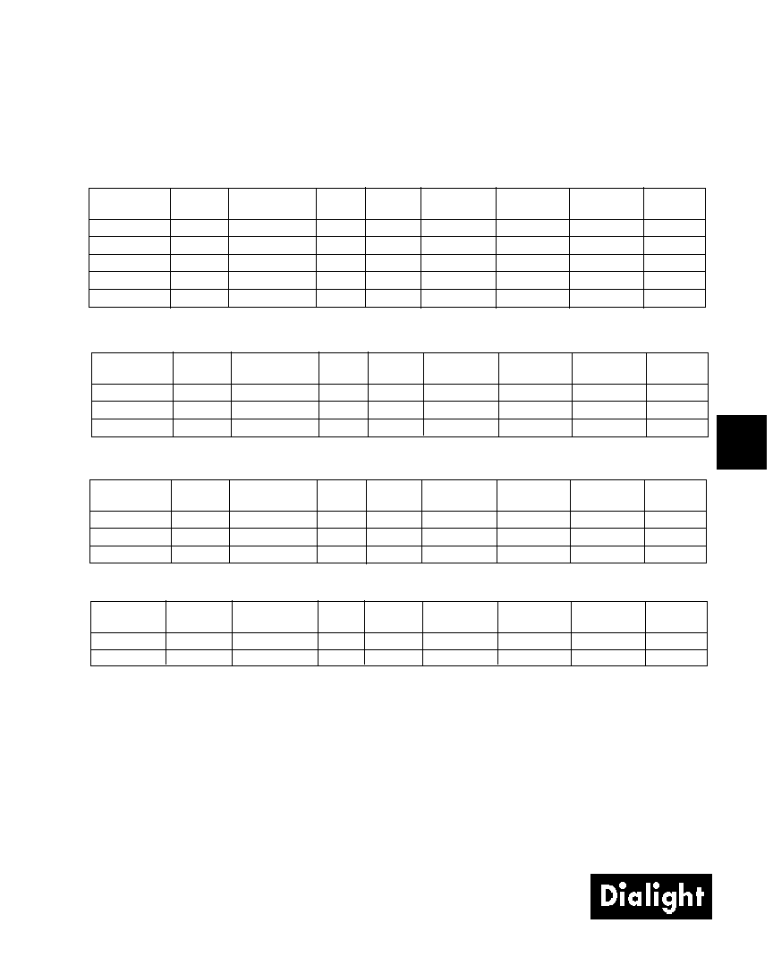
Peak
I
V
V
F
Test
Viewing
LED
Part Number
Color
Wavelength nm
mcd
Volts
Current (mA)
Angle 2
˝
Data sheet
Page #
551-0201
Green
565
12.6
2.1*
10
60°
521-9210
4-58
551-0301
Yellow
585
10
2.1*
10
60°
521-9211
4-58
551-0401
Red
635
10
2*
10
60°
521-9216
4-58
551-0801
Blue
428
12
3.5
10
70°
521-9831
4-57
551-2501
Orange
600
7
2.2
10
60°
521-9498
4-58
HIGH EFFICIENCY
Peak
I
V
V
F
Test
Viewing
LED
Part Number
Color
Wavelength nm
mcd
Volts
Current (mA)
Angle 2
˝
Data sheet
Page #
551-1101
Red
635
1.6
1.7
2
60°
521-9324
4-60
551-1201
Yellow
585
1.6
1.8
2
60°
521-9325
4-60
551-1301
Green
565
1.6
1.9
2
60°
521-9326
4-60
LOW CURRENT
Peak
I
V
Test
Forward
Viewing
LED
Part Number
Color
Wavelength nm
mcd
Voltage
Current (mA)
Angle 2
˝
Data sheet
Page #
551-0501
Red
635
29
5
10
60°
521-9215
4-59
551-0601
Green
565
19
5
10
60°
521-9323
4-59
551-0701
Yellow
585
12.6
5
10
60°
521-9322
4-59
INTEGRAL RESISTOR, 5 VOLTS
Peak
I
V
V
F
Test
Viewing
LED
Part Number
Color
Wavelength nm
mcd
Volts
Current (mA)
Angle 2
˝
Data sheet
Page #
551-3001
Red/Green
635/565
5
2
10
50°
521-9459
4-63
551-3101
Yellow/Green
585/565
4.3/6.3
2.1*/2.1*
10
80°
521-9478
4-62
BI-COLOR
* IF = 20mA
* IF = 20mA
Typical Operating Characteristics (T
A
=25°C)
See LED data sheet for additional information
See page 4-70 and 4-71 for Reference Only LED Drive Circuit Examples. See page 4-72 for Pin Out
4-57
Dialight Corporation · 1501 Route 34 South · Farmingdale, NJ 07727 · TEL: (732) 919-3119 · FAX: (732) 751-5778 ·www.dialight.com
4
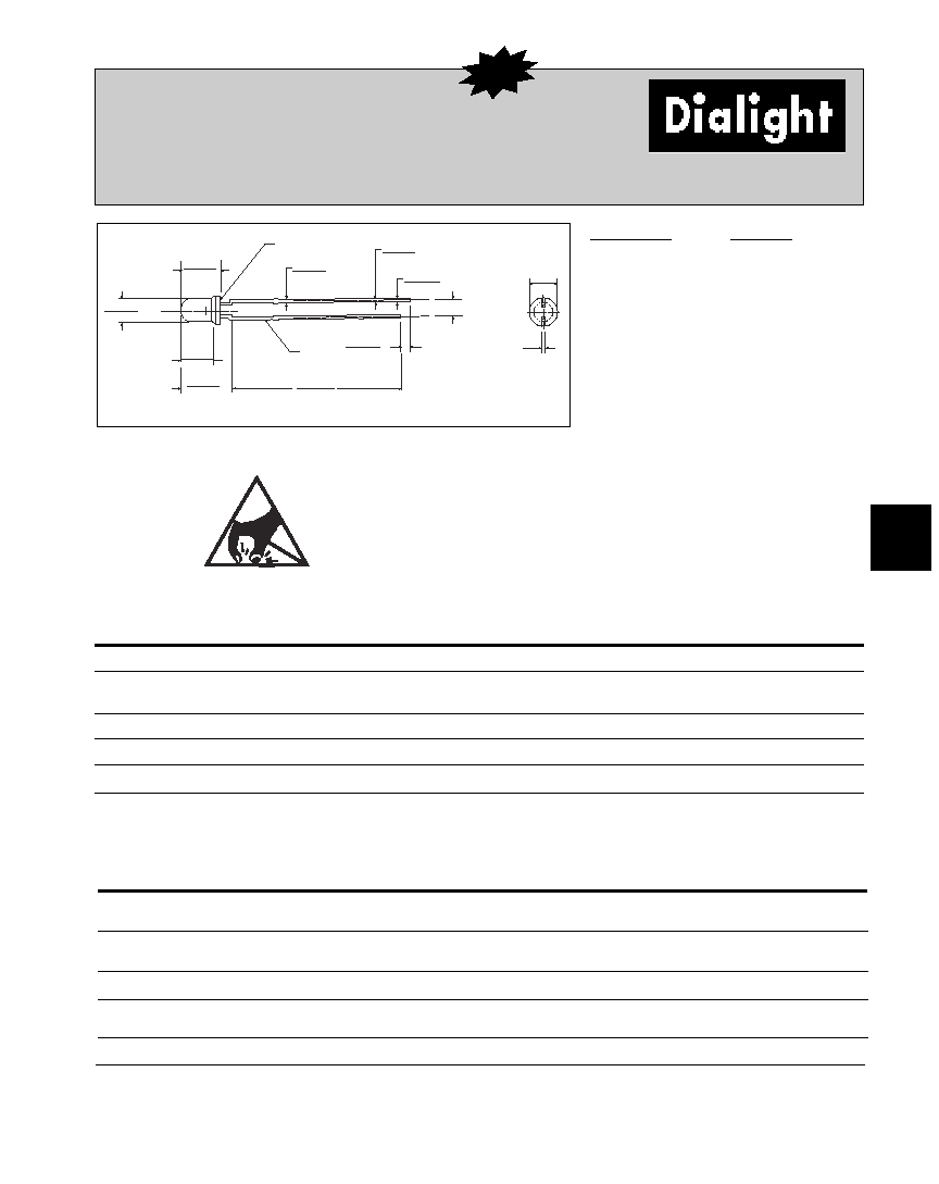
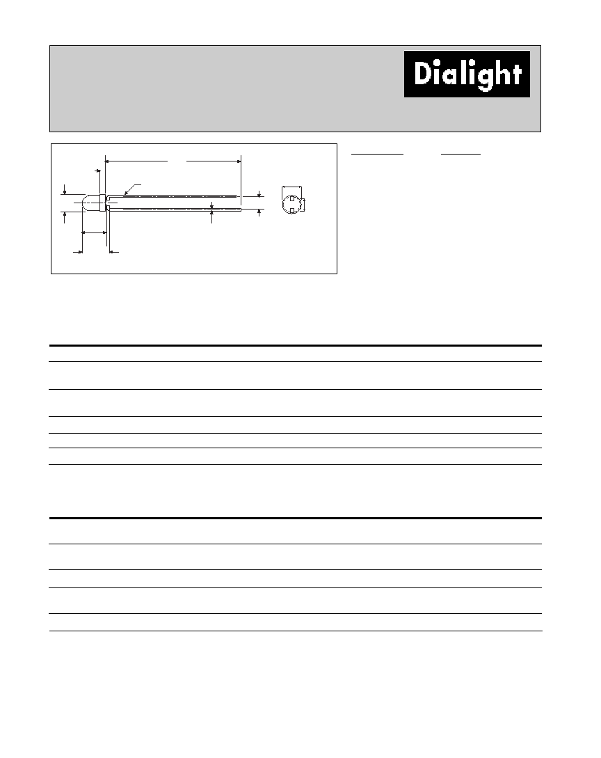
3mm Discrete LED
Tinted, Diffused
521-9831
3.4 [.134]
3.1 [.122]
0.6 [.024]
0.4 [.016]
ř
2.9 [.114]
2.7 [.106]
4.8 [.189]
4.4 [.173]
3.7 [.145]
3.5 [.138]
6.1 [.240]
5.7 [.224]
29 [1.142]
27 [1.063]
1.8 [.071]
1.2 [.047]
CATHODE
2.54 [.100]
0.6 [.024]
0.4 [.016]
0.7 [.028]
0.4 [.016]
4.8 [.189]
4.4 [.173]
SURFACE NOT FLAT
PART NO.
COLOR
521-9831
Blue
ł
Blue
ABSOLUTE MAXIMUM RATINGS
(TA=25°C)
-9831
Power Dissipation (mW)
100
Forward Current (mA)
20
Derating (mA/°C)
From 55°C
.44
Operating Temperature (°C)
-40/+100
Storage Temperature (°C)
-40/+100
Soldering Temperature
260°C, 5 seconds, 1.6 mm from case
Blue
OPERATING CHARACTERISTICS
(TA=25°C)
-9831
Luminous Intensity (mcd)
Min.
6.3
IF=10mA
Typical
12
Peak Wavelength (nm)
Typical
428
Peak
Viewing Angle (2
˝)
Typical
70°
Forward Voltage (V)
Typical
3.5
IF=10mA
Max.
4.2
Reverse Voltage (V) IR=10µA
Min.
3
Dimensions in mm [inches]
is the off axis angle at which the luminous intensity is half the axial luminous intensity
Solder Adherence per MIL-STD-202E, Method 208C
MOUNTING CLIP: 515-0006
located on page 4-65
ATTENTION
OBSERVE PRECAUTIONS
FOR HANDLING
ELECTROSTATIC
SENSITIVE
DEVICES
ł
NEW
4-58
Dialight Corporation · 1501 Route 34 South · Farmingdale, NJ 07727 · TEL: (732) 919-3119 · FAX: (732) 751-5778 ·www.dialight.com
Green
Yellow
Red
Orange
Red
ABSOLUTE MAXIMUM RATINGS
(T
A
=25°C)
-9210
-9211
-9216
-9498
-9636
Power Dissipation (mW)
100
60
100
135
100
Forward Current (mA)
30
20
30
25
40
Derating (mA/°C)
From 50°C
1
from 25°C
.4
.25
.4
.5
.5
1
Operating Temperature (°C)
-55/+100
-55/+100
-55/+100
-55/+100
-55/+100
Storage Temperature (°C)
-55/+100
-55/+100
-55/+100
-55/+100
-55/+100
Soldering Temperature
260°C, 5 seconds, 1.6 mm from body
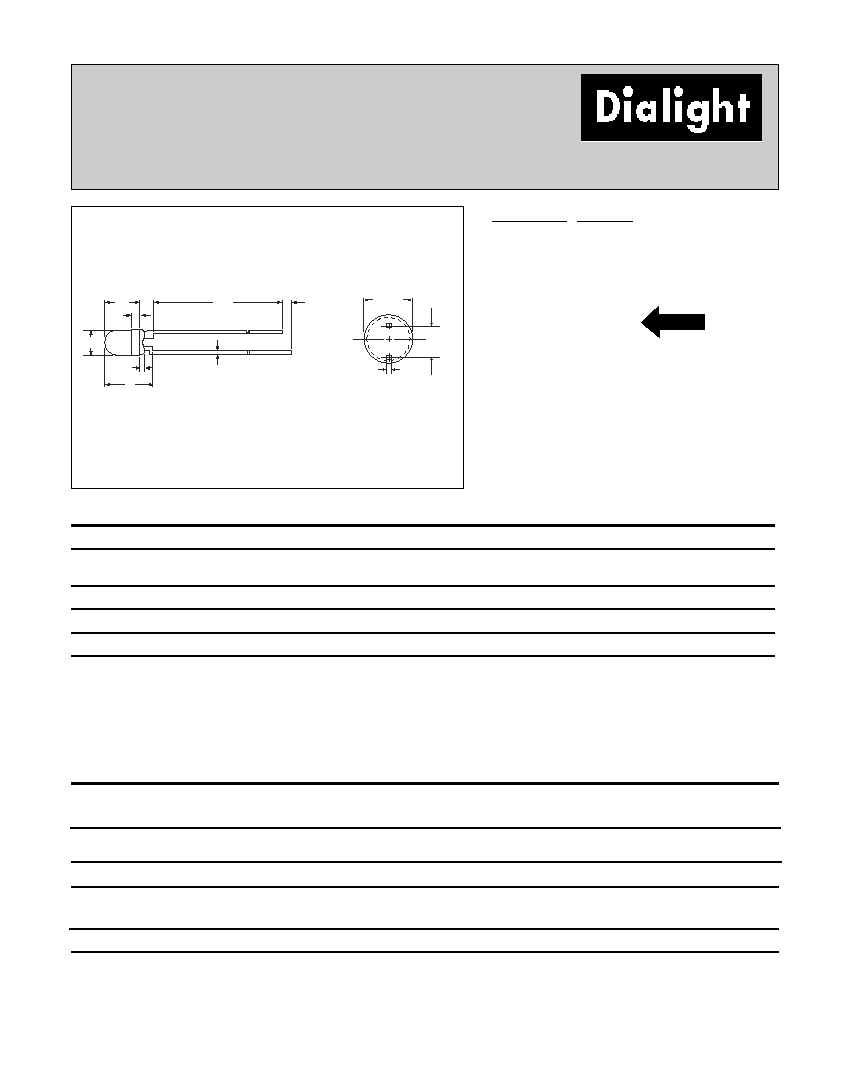
3mm Discrete LED
High Efficiency
Diffused
521-9210, -9211, -9216, -9498, -9636
4.45
[.175]
1.02
[.040]
3.00
[.118]
1.50
[.059]
MAX
6.00
[.236]
25.4
[1.0] MIN
1.02
[.040]
MIN
.45
[.016 ]
.40
[.016]
2.54
[.100]
3.30
[.13]
PART NO. COLOR
521-9210
Green
521-9211
Yellow
521-9216
Red
521-9498
Orange
521-9636
Red
Green
Yellow
Red
Orange
Red
OPERATING CHARACTERISTICS
(T
A
=25°C)
-9210
-9211
-9216
-9498
-9636
Luminous Intensity (mcd)
Min.
4.7
7.4
7.4
3.4
8.7
1
IF=10mA
1
IF=20mA
Typical
12.6
10
10
7
48
1
Peak Wavelength (nm)
Typical
565
585
635
600
660
Peak
Viewing Angle (2
˝
)
Typical
60°
60°
60°
60°
60°
Forward Voltage (V)
Typical
2.1
1
2.1
1
2
1
2.2
1.8
1
IF=10mA
1
IF=20mA
Max.
2.8
1
2.8
1
2.8
1
3
2.4
1
Reverse Voltage (V), IR=100µA
Max.
5
5
5
5
4
Dimensions in mm [inches]
is the off axis angle at which the luminous intensity is half the axial luminous intensity
Solder Adherence per MIL-STD-202E, Method 208C
MOUNTING CLIP: 515-0006
located on page 4-65
short lead cathode all colors except 521-9636 Red.
For 521-9636 Red, short lead is anode.
NEW
4-59
Dialight Corporation · 1501 Route 34 South · Farmingdale, NJ 07727 · TEL: (732) 919-3119 · FAX: (732) 751-5778 ·www.dialight.com
4
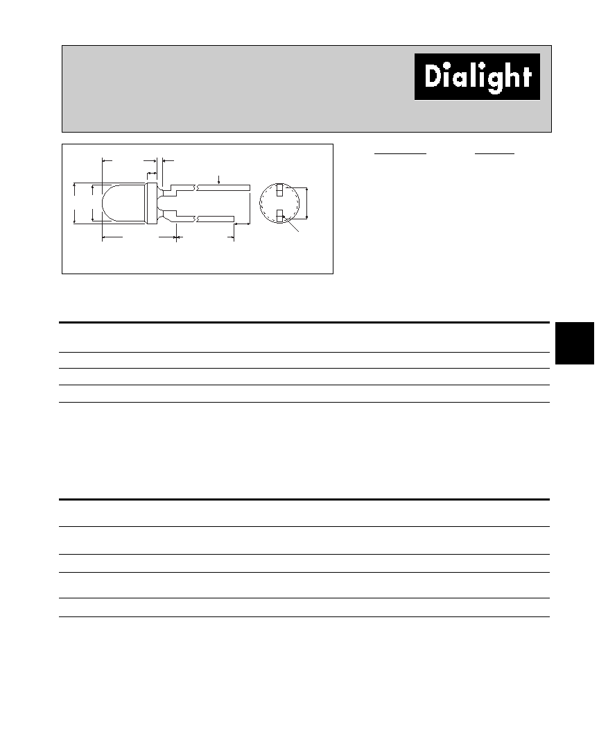
3mm Discrete LED
Integral Resistor, 5V
Diffused
521-9215, -9322, -9323
4.40 [.175]
2.54
[.100]
2.90
[.115]
3.20
[.125]
1.01
[.040]
5.97 [.235]
2.41 [.950] MAX
1.27
[.050]
.457
[.018]
SQ.
CATHODE
1.0
[.040]
PART NO.
COLOR
521-9215
Red
521-9322
Yellow
521-9323
Green
Red
Yellow
Green
ABSOLUTE MAXIMUM RATINGS
(T
A
=25°C)
-9215
-9322
-9323
Forward Voltage (V)
7.5
7.5
7.5
Derating (V/°C)
From 50°C
.086
.086
.071
Operating Temperature (°C)
-40/+85
-40/+85
-20/+85
Storage Temperature (°C)
-55/+100
-55/+100
-55/+100
Soldering Temperature
260°C, 5 seconds, 1.6 mm from case
Red
Yellow
Green
OPERATING CHARACTERISTICS
(T
A
=25°C)
-9215
-9322
-9323
Luminous Intensity (mcd)
Min.
8.7
3.7
5.6
VF=5V
Typical
29
12.6
19
Peak Wavelength (nm)
Typical
635
585
565
Peak
Viewing Angle (2
˝)
Typical
60°
60°
60°
Forward Current (mA)
Typical
10
10
10
VF=5V
Max.
20
20
20
Reverse Voltage (V), IR=100µA
Min.
5
5
5
Dimensions in mm [inches]
is the off axis angle at which the luminous intensity is half the axial luminous intensity
Solder Adherence per MIL-STD-202E, Method 208C
MOUNTING CLIP: 515-0006
located on page 4-65
4-60
Dialight Corporation · 1501 Route 34 South · Farmingdale, NJ 07727 · TEL: (732) 919-3119 · FAX: (732) 751-5778 ·www.dialight.com
3mm Discrete LED
Low Current
Diffused
521-9324, -9325, -9326
4.4
[.175]
1.01
[.040]
5.97
[.235]
26.67
[1.05]
MIN.
1.00
[.040]
.40
[.016]
3.3
[.130]
2.54
[.100]
.40
[.016]
CATHODE
1.0
[.040]
PART NO.
COLOR
521-9324
Red
521-9325
Yellow
521-9326
Green
Red
Yellow
Green
ABSOLUTE MAXIMUM RATINGS
(T
A
=25°C)
-9324
-9325
-9326
Power Dissipation (mW)
20
20
20
Forward Current (mA)
7
7
7
Derating (mA/°C)
From 90°C
.7
.7
.7
Peak Current (mA)
500
500
500
Pulse width = 10 µs
Operating Temperature (°C)
-55/+100
-55/+100
-55/+100
Storage Temperature (°C)
-55/+100
-55/+100
-55/+100
Soldering Temperature
260°C, 5 seconds, 1.6 mm from case
Red
Yellow
Green
OPERATING CHARACTERISTICS
(T
A
=25°C)
-9324
-9325
-9326
Luminous Intensity (mcd)
Min.
1
1
1
IF=2mA
Typical
1.6
1.6
1.6
Peak Wavelength (nm)
Typical
635
585
565
Peak
Viewing Angle (2
˝
)
Typical
60°
60°
60°
Forward Voltage (V)
Typical
1.7
1.8
1.9
IF=2mA
Max.
2.2
2.7
2.2
Reverse Voltage (V), IR=50µA
Min.
5
5
5
Dimensions in mm [inches]
is the off axis angle at which the luminous intensity is half the axial luminous intensity
Solder Adherence per MIL-STD-202E, Method 208C
MOUNTING CLIP: 515-0006
located on page 4-65
4-62
Dialight Corporation · 1501 Route 34 South · Farmingdale, NJ 07727 · TEL: (732) 919-3119 · FAX: (732) 751-5778 ·www.dialight.com
3mm Discrete LED
Bi-Color
Non-Tinted, Diffused
521-9478, -9628, -9768
3.20
[.126]
MAX
4.45
[.175]
5.20
±
.5
[.205
±
.02]
1.02
[.040]
3.00
[.118]
25.40
[1.00]
MIN
RED CATHODE 521-9768
YELLOW CATHODE 521-9478
GREEN CATHODE 521-9628
.50
[.020]
TYP
2.54
[.100]
NOM
2.54
[.100]
NOTE:
MENISCUS MAY EXTEND 1.0MM [.040]
DOWN FROM HOUSING
PART NO.
COLOR
521-9478
Yellow/Green
521-9628
Red/Green
521-9768
Red/Yellow
Yellow/Green
Red/Green
Red/Yellow
ABSOLUTE MAXIMUM RATINGS
(TA=25°C)
-9478
-9628
-9768
Power Dissipation (mW)
60/100
140/100
100/60
Forward Current (mA)
20/30
40/30
30/20
Derating (mA/°C)
From 25°C
1
From 50°C
.25
1
/.40
1
.5/.4
.4
1
/.25
1
Peak Current (mA)
80/120
200/120
120/80
Pulse width = 10µs
Operating Temperature (°C)
-55/+100
-55/+100
-55/+100
Storage Temperature (°C)
-55/+100
-55/+100
-55/+100
Soldering Temperature
260°C, 5 seconds, 1.66 mm from case
Yellow/Green
Red/Green
Red/Yellow
OPERATING CHARACTERISTICS
(TA=25°C)
-9478
-9628
-9768
Luminous Intensity (mcd)
Min.
2.5/2.5
3.7*/1.1*
1.7*/1.7*
IF=10mA * IF=20mA
Typical
4.3/6.3
12.6*/3.7*
5.6*/5.6*
Peak Wavelength (nm)
Typical
585/565
660/565
630/585
Peak
Viewing Angle (2
˝
)
Typical
80°
200°
80°
Forward Voltage (V)
Typical
2.1/2.1
1.8/2.1
2/2.1
IF=20mA
Max.
2.8/2.8
2.4/2.8
2.8/2.8
Reverse Voltage (V) IR=100ua
Min.
5
5
5
Dimensions in mm [inches]
is the off axis angle at which the luminous intensity is half the axial luminous intensity
Solder Adherence per MIL-STD-202E, Method 208C
MOUNTING CLIP: 515-0006
located on page 4-65

4-63
Dialight Corporation · 1501 Route 34 South · Farmingdale, NJ 07727 · TEL: (732) 919-3119 · FAX: (732) 751-5778 ·www.dialight.com
4
3mm Discrete LED
Bi-Color
Non-Tinted, Diffused
521-9459
2.54
[.100]
3.00
[.118]
4.59 [.181]
6.10 [.240]
.50
[.020] SQ.
NOM.
26.92 [1.06] MIN
3.40
[.134]
MAX
CATHODE
GREEN
1.80
[.071]
MAX
4.0
[.158]
1.0
[.040]
PART NO.
COLOR
521-9459
Red/Green
Red/Green
ABSOLUTE MAXIMUM RATINGS
(TA=25°C)
-9459
Power Dissipation (mW)
140
Forward Current (mA)
45
Derating (mA/°C)
From 25°C
.6
Peak Current (mA)
1000
Pulse width = 10µs
Operating Temperature (°C)
-55/+100
Storage Temperature (°C)
-55/+100
Soldering Temperature
260°C, 5 seconds, 1.6 mm from case
Red/Green
OPERATING CHARACTERISTICS
(TA=25°C)
-9459
Luminous Intensity (mcd)
Min.
2.5/3.7
IF=10mA
Typical
4.7/10
Peak Wavelength (nm)
Typical
635/565
Peak
Viewing Angle (2
˝)
Typical
50°
Forward Voltage (V)
Typical
2/2.1
IF=10mA
Max.
2.8/2.8
Dimensions in mm [inches]
is the off axis angle at which the luminous intensity is half the axial luminous intensity
Solder Adherence per MIL-STD-202E, Method 208C
MOUNTING CLIP: 515-0006
located on page 4-65