TECHNICAL SPECIFICATIONS OF SURFACE MOUNT SCHOTTKY BARRIER RECTIFIER
VOLTAGE RANGE - 20 to 40 Volts CURRENT - 1.0 Ampere
FEATURES
* Ideal for surface mounted applications
* Low leakage current for high efficiency
MAXIMUM RATINGS AND ELECTRICAL CHARACTERISTICS
Ratings at 25
o
C ambient temperature unless otherwise specified.
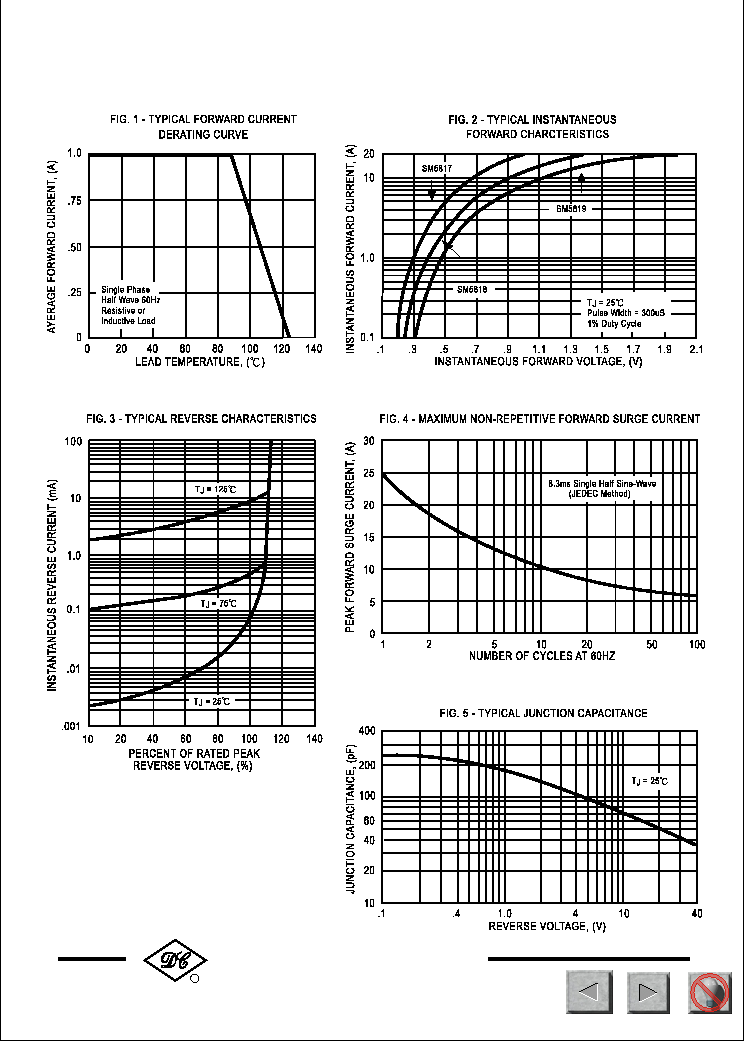
Single phase, half wave, 60 Hz, resistive or inductive load.
For capacitive load, derate current by 20%.
SM5817
THRU
SM5819
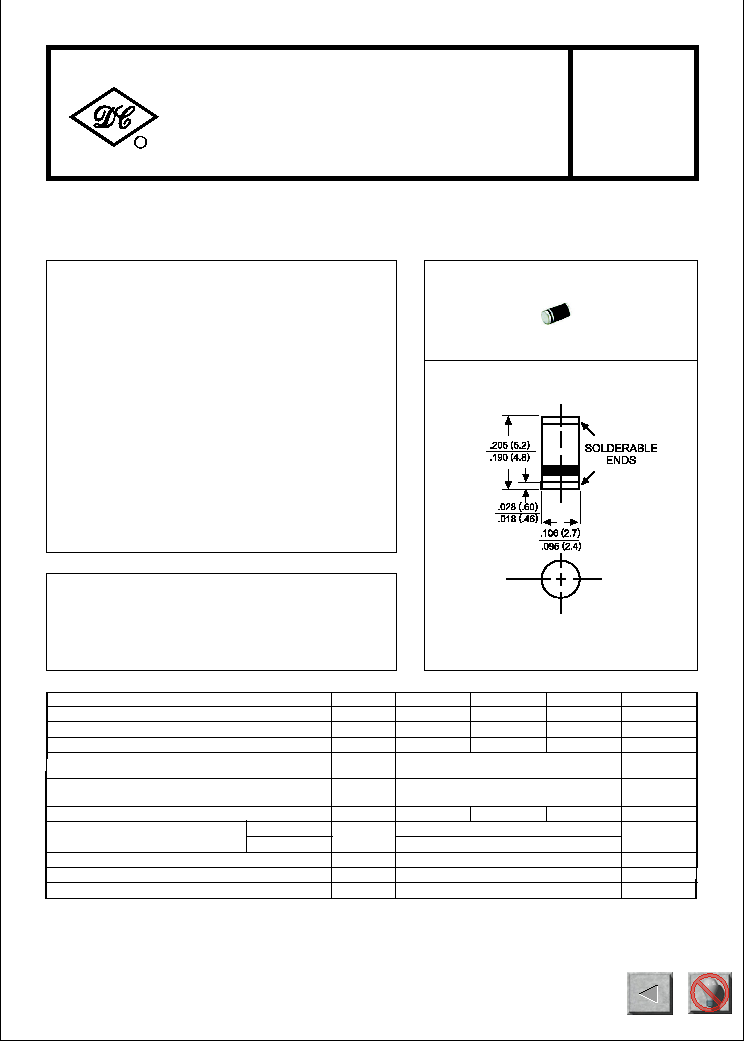
SM-1(DO-213AB)
NOTES : 1. Thermal Resistance (Junction to Ambient), .24in
2
(6.0mm
2
) copper pads to each terminal.
2. Measured at 1 MHz and applied reverse voltage of 4.0 volts.
Dimensions in inches and (millimeters)
Maximum Recurrent Peak Reverse Voltage
Maximum RMS Voltage
Maximum DC Blocking Voltage
Maximum Average Forward Rectified Current
at T
A
=90
o
C
Peak Forward Surge Current 8.3 ms single half sine-wave
superimposed on rated load (JEDEC Method)
Typical Thermal Resistance (Note1)
Typical Junction Capacitance (Note 2)
SYMBOL
V
RRM
V
DC
I
FSM
C
J
T
J
, T
STG
V
RMS
UNITS
20
Volts
Volts
Volts
Amps
14
28
40
1.0
25
Amps
0
C/ W
0
C
30
21
Storage Operating Temperature Range
R
J A
I
O
-65 to + 125
pF
20
30
40
SM5817
SM5818
SM5819
Maximum DC Reverse Current at
Rated DC Blocking Voltage
V
F
I
R
mAmps
Maximum Instantaneous Forward Voltage at 1.0A DC
1.0
.45
.55
.60
10
@T
A
= 25
o
C
@T
A
= 100
o
C
RECTIFIER SPECIALISTS
R
DC COMPONENTS CO., LTD.
MECHANICAL DATA
* Case: Molded plastic
* Epoxy: UL 94V-0 rate flame retardant
* Mounting position: Any
* Weight: 0.12 gram
*Terminals: Solder plated solderable per
MIL-STD-202E, Method 208 guaranteed
* Polarity: Color band denotes cathode end
* High current capability
75
110
276
NEXT
BACK
EXIT
NEXT
BACK
EXIT