
1 of 18
102199
FEATURES
§
Low impedance coupler to create large
common-ground, multi-level MicroLAN
networks
§
Keeps inactive branches pulled high to 5V
§
Simplifies network topology analysis by
logically decoupling devices on active
network segments
§
Conditional search for fast event signaling
§
Auxiliary 1-Wire
TM
line to connect a memory
chip or to be used as digital input
§
Programmable, general purpose open drain
control output
§
Communicates at 16.3k bits per second
§
Unique, factory-lasered and tested 64-bit
registration number (8-bit family code + 48-
bit serial number + 8-bit CRC tester) assures
absolute traceability because no two parts are
alike
§
8-bit family code specifies device
communication requirements to bus master
§
Built-in multidrop controller ensures
compatibility with other MicroLAN products
§
Operating temperature range from -40°C to
+85°C
§
Compact, low cost 6-pin TSOC surface mount
package
PIN ASSIGNMENT
PIN DESCRIPTION
Pin 1
GND
Pin 2
1-Wire in
Pin 3
Main 1-Wire out
Pin 4
Auxiliary 1-Wire out
Pin 5
Control Output
Pin 6
V
DD
ORDERING INFORMATION
DS2409P
6-pin TSOC package
DESCRIPTION
The MicroLAN coupler is an essential component to build and control 1-Wire MicroLAN networks with
multi-level branching. In contrast to approaches that switch the ground line, the coupler maintains a
common ground level for the whole network and keeps the inactive segments powered. This simplifies
supplying central or local power for additional circuitry and prevents loss of status of parasitically
powered devices. It also avoids disrupting communication caused by the parasitic power supply of 1-Wire
devices after activating a branch. The coupler does not contain any user-programmable memory. To label
a branch one can connect any 1-Wire memory device to the auxiliary 1-Wire output of the coupler. Both
the main and the auxiliary 1-Wire output are supported by a "smart-on" command. This command
generates a reset/presence sequence on the selected output before the electronic switch closes the contact
to the 1-Wire bus. This way the bus master can apply a ROM function command (optionally followed by
a memory function) to the devices on the just activated segment with all other devices in the network
DS2409
MicroLAN Coupler
www.dalsemi.com
1
2
3
6
5
4
TOP VIEW
3.7 X 4.0 X 1.5 mm
SIDE VIEW
6-PIN TSOC PACKAGE
DS2409
102199
2 of 18
remaining deselected. This significantly speeds up the analysis of topology and population in a
continuously changing network. The coupler also supports the bus master in detecting arrivals on the
inactive segments of the network by responding to the conditional search command. The control output
can be used to optically signal the on/off state of a branch or, together with the auxiliary output, for
handshaking in dual-master applications. The network size can be maximized by using a DS2480 line
driver at the bus master's serial interface. The DS2480 compensates for the rising ground level caused by
the non-zero on-resistance of couplers in multi-level networks.
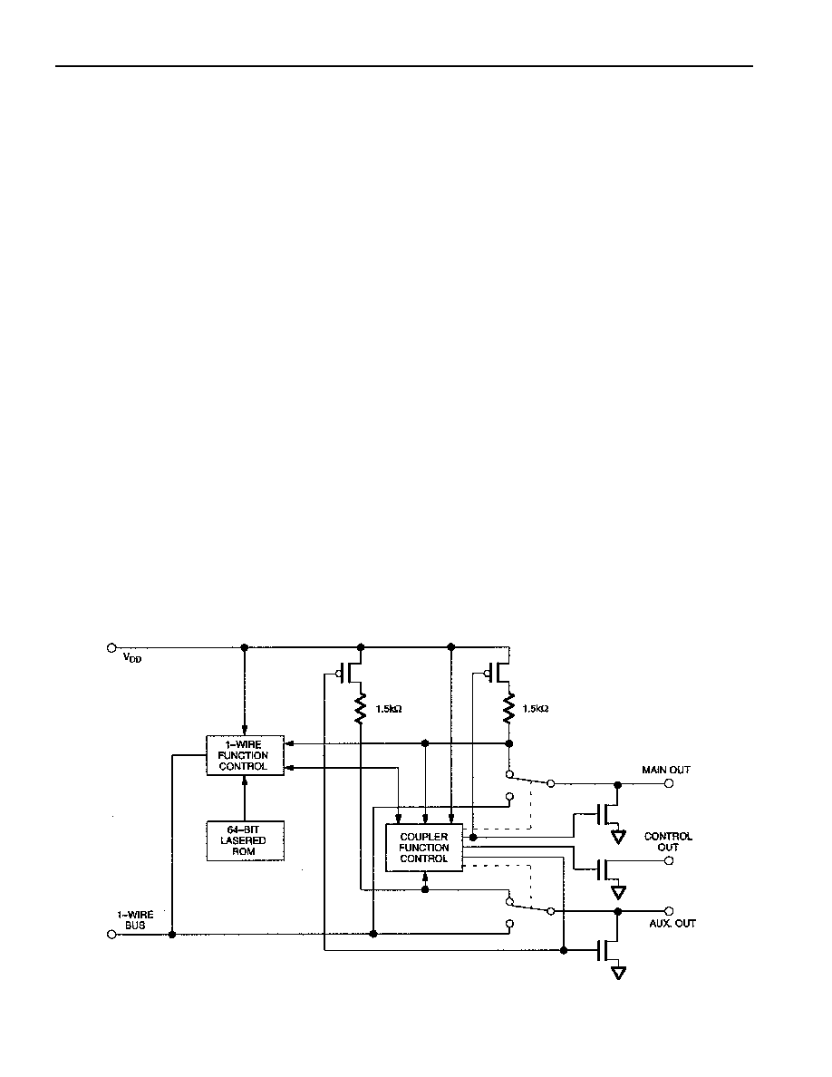
OVERVIEW
The DS2409 Coupler provides a means to create large MicroLAN networks with additional control
capability provided by an open-drain N-channel MOSFET that can be remotely switched via
communication over the 1-Wire bus (Figure 1). An auxiliary output can be used to label the branch by
connecting a programmed 1-Wire memory chip or as digital input. The DS2409 contains a factory-lasered
registration number that includes a unique 48-bit serial number, an 8-bit CRC, and an 8-bit family code
(1FH). The 64-bit ROM portion of the DS2409 not only creates an absolutely unique electronic
identification for the device itself but also is a means to locate and address the device in order to exercise
its control functions.
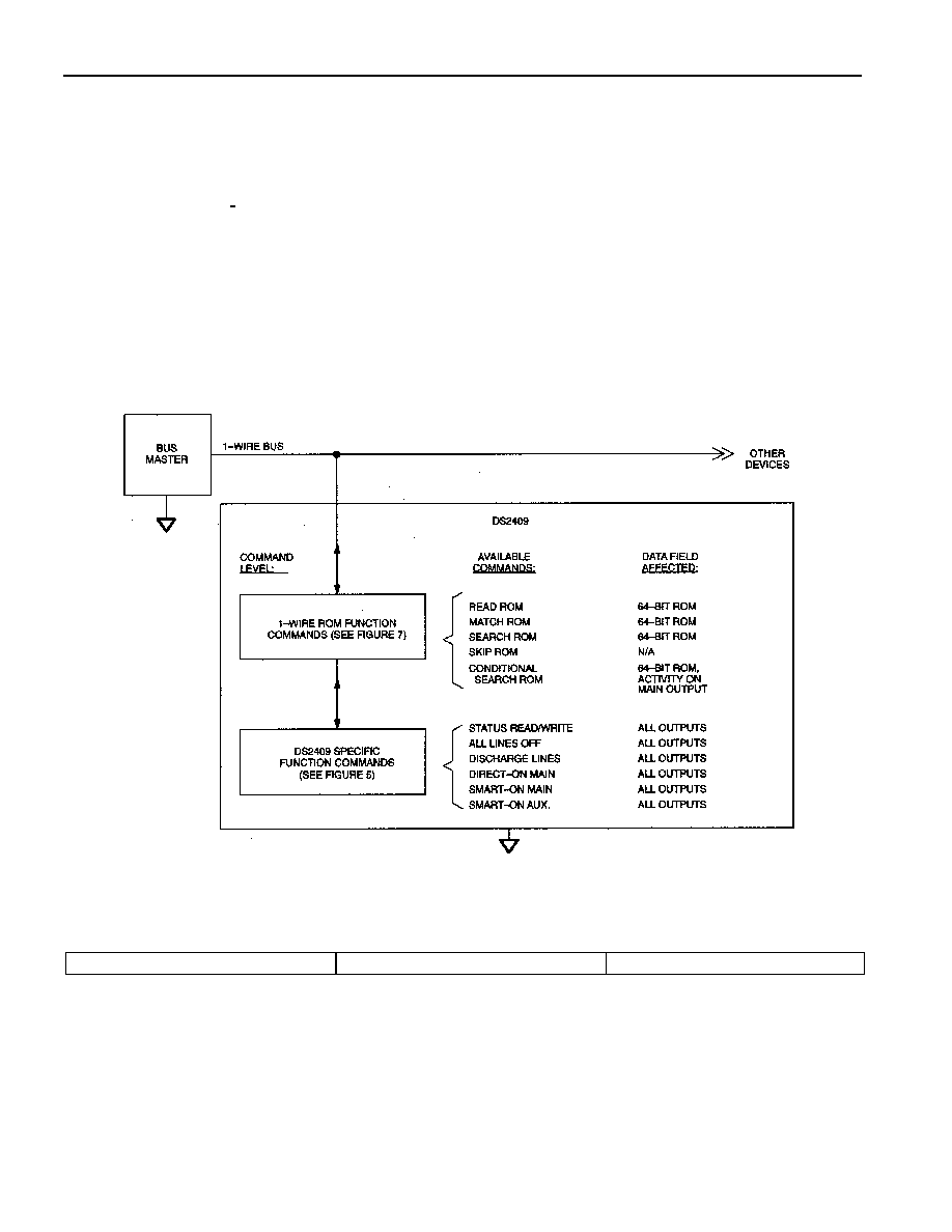
The DS2409 uses the standard Dallas Semiconductor 1-Wire protocol for data transfers (Figure 2), with
all data being read and written least significant bit first. Communication to and from the DS2409 requires
a single bi-directional line that is typically a port pin of a microcontroller. The 1-Wire bus master
(microcontroller) must first issue one of five ROM function commands: 1) Read ROM, 2) Match ROM,
3) Search ROM, 4) Skip ROM, or 5) Conditional Search ROM. These commands operate on the 64-bit
lasered ROM portion of each device and can singulate a specific device if many are present on the 1-Wire
line as well as indicate to the bus how many and what type of each device is present. After a ROM
function command is successfully executed, the control functions of the device can be exercised via the 1-
Wire bus.
BLOCK DIAGRAM Figure 1
DS2409
102199
3 of 18
64-BIT LASERED ROM
Each DS2409 contains a unique ROM code that is 64 bits long. The first eight bits are a 1-Wire family
code. The next 48 bits are a unique serial number. The last eight bits are a CRC of the first 56 bits. (See
Figure 3.) The 1-Wire CRC of the lasered ROM is generated using the polynomial X
8
+ X
5
+ X
4
+ 1.
Additional information about the Dallas Semiconductor 1-Wire Cyclic Redundancy Check is available in
the Book of DS19xx iButton Standards. The 64-bit ROM and ROM Function Control section allow the
DS2409 to operate as a 1-Wire device and follow the 1-Wire protocol detailed in the section "1-Wire Bus
System". The functions required to exercise the control functions of the DS2409 are not accessible until
the ROM function protocol has been satisfied. This protocol is described in the ROM functions flow
chart (Figure 7). The 1-Wire bus master must first provide one of the five ROM function commands.
After a ROM function sequence has been successfully executed, the bus master may then provide any one
of the function commands specific to the DS2409 (Figure 5).
HIERARCHICAL STRUCTURE FOR 1-WIRE PROTOCOL Figure 2
64-BIT LASERED ROM Figure 3
MSB
LSB
8-Bit CRC Code
48-Bit Serial Number
8-Bit Family Code (1FH)
MSB
LSB MSB
LSB MSB
LSB

DS2409
102199
4 of 18
1-WIRE CRC GENERATOR Figure 4
CONTROL FUNCTION COMMANDS
The "Control Function Flow Chart" (Figure 5) describes the protocols necessary for controlling the main
and auxiliary output as well as the control output of the DS2409. The 1-Wire Function Control section
and the Coupler Function Control section combine to interpret the commands issued by the bus master
and create the correct control signals within the device. Depending on the complexity of function to be
exercised, the 1-byte command code may require one or two more bytes being sent by the bus master.
Switching one branch on implies that the other branch is automatically switched off. At power-on, both
branches are switched off. Each command flow includes at least one byte of feedback information for the
bus master to check if the command was understood and executed.
STATUS READ/WRITE [5Ah]
This command should be sent to the device after powering up unless the default settings are adequate for
the application. Following the command code, the bus master has to send the status control byte. The bus
master will then read the status info byte from the device. The confirmation byte is identical to the status
info byte. Tables 1 and 2 show the bit assignments in both bytes.
At power-on the device will be in the auto-control mode and the control output will be assigned to the
main output. The control output can be assigned to the auxiliary output by setting bit 6 of the status
control byte to a 1. For manual operation of the control output one has to select manual mode (bit 5 = 1).
The value of bit 7 of the status control byte will then determine the status of the control output. A 1 for bit
7 will make the transistor conducting, a 0 will turn it off (non-conducting). To change the status of the
device, both bits 3 and 4 of the status control byte have to be 0. Otherwise the settings will remain
unchanged. In any case, the status info byte will reflect the currently valid settings including the changes
that might have been made with the status control byte.
The status info byte allows the bus master to verify the actual status of each output (STAT,
active/inactive, on/off) and the static level at the main and auxiliary output (LEVL, 1 for normal, 0 in case
of a short). If a 1-Wire output is inactive and a low-going edge is encountered during this time, the
DS2409 will set the event flag (EVNT) the status info byte. Each output has its own event flag. The event
flags are cleared with the All Lines Off command. Bit 7 of the status info byte tells if the device is auto-
control mode or manual mode. Depending on the value of this bit, the information in bit 6 (CNTR.
STAT) either reports the association of the control output to a particular output (auto-control mode) or the
status of the transistor at the control output.
DS2409
102199
5 of 18
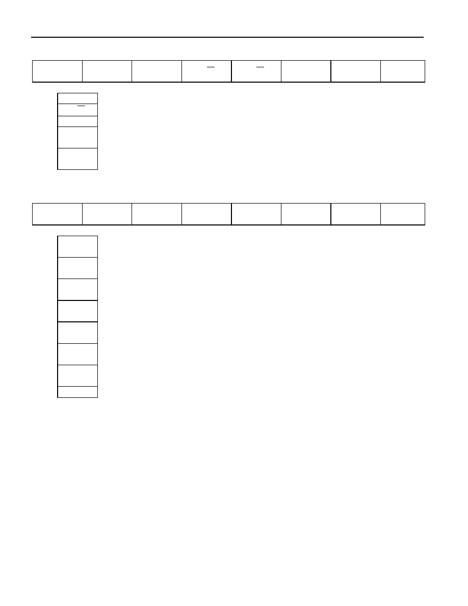
STATUS CONTROL BYTE Table 1
7
6
5
4
3
2
1
0
DATA
X
CNTR.
SEL.
MODE
R/
W
R/
W
X
X
X
0-2
X
don't care
3-4
R/
W
Write control: both bits must be 0 to change the status.
5
MODE
control output mode selection: 0 = auto-control mode (default), 1 = manual mode
6
CNTR.
SEL.
control output association (auto-control mode): 0 = main (default), 1 = auxiliary
7
DATA
X
Value to be written to control output (manual mode only): don't care otherwise
STATUS INFO BYTE Table 2
7
6
5
4
3
2
1
0
MODE
CNTR.
STAT
EVNT
AUX.
EVNT
MAIN
AUX.
LEVL
AUX.
STAT
MAIN
LEVL
MAIN
STAT
0
MAIN
STAT
status of main output: 0 = active (connected to bus master), 1 = inactive
1
MAIN
LEVL
voltage sensed at main output: 0 = low, 1 = high (see note)
2
AUX.
STAT
status of auxiliary output: 0 = active (connected to bus master), 1 = inactive
3
AUX.
LEVL
voltage sensed at auxiliary output: 0 = low, 1 = high (see note)
4
EVNT
MAIN
event flag for main output: 0 = no event, 1 = negative edge sensed since inactive
5
EVNT
AUX.
event flag for aux. Output: 0 = no event, 1 = negative edge sensed since inactive
6
CNTR.
STAT
if auto-control mode: control output association, 0 = main, 1 = auxiliary
if manual mode: 0 = output transistor off, 1 = output transistor on
7
MODE
control output mode: 0 = auto-control mode, 1 = manual mode
Note: Data is valid only if the output is decoupled from the 1-Wire input.
ALL LINES OFF [66h]
This command is used to deactivate the currently active 1-Wire output and to clear both event flags or to
end a discharge cycle initiated by the Discharge Lines command. Before issuing this command, one
should read the status and check the event flags of both, the main and the auxiliary output. Otherwise one
might inadvertently clear the event flag without having taken appropriate action. If the DS2409 is in auto-
control mode, the transistor at the control output will be switched off (non-conducting). At power-on, the
device will automatically perform the All Lines Off command. In contrast to a power-on cycle, the All
Lines Off command does not clear the Mode and Control Select bits.