1 of 16
112099
FEATURES
Requires no external components
Measures temperatures from -55°C to +125°C
in 1°C increments. Fahrenheit equivalent is -
67°F to +257°F in 1.8°F increments
DS1821
Converts temperature to digital word in 1
second (max.)
Thermostatic settings are user definable and
nonvolatile
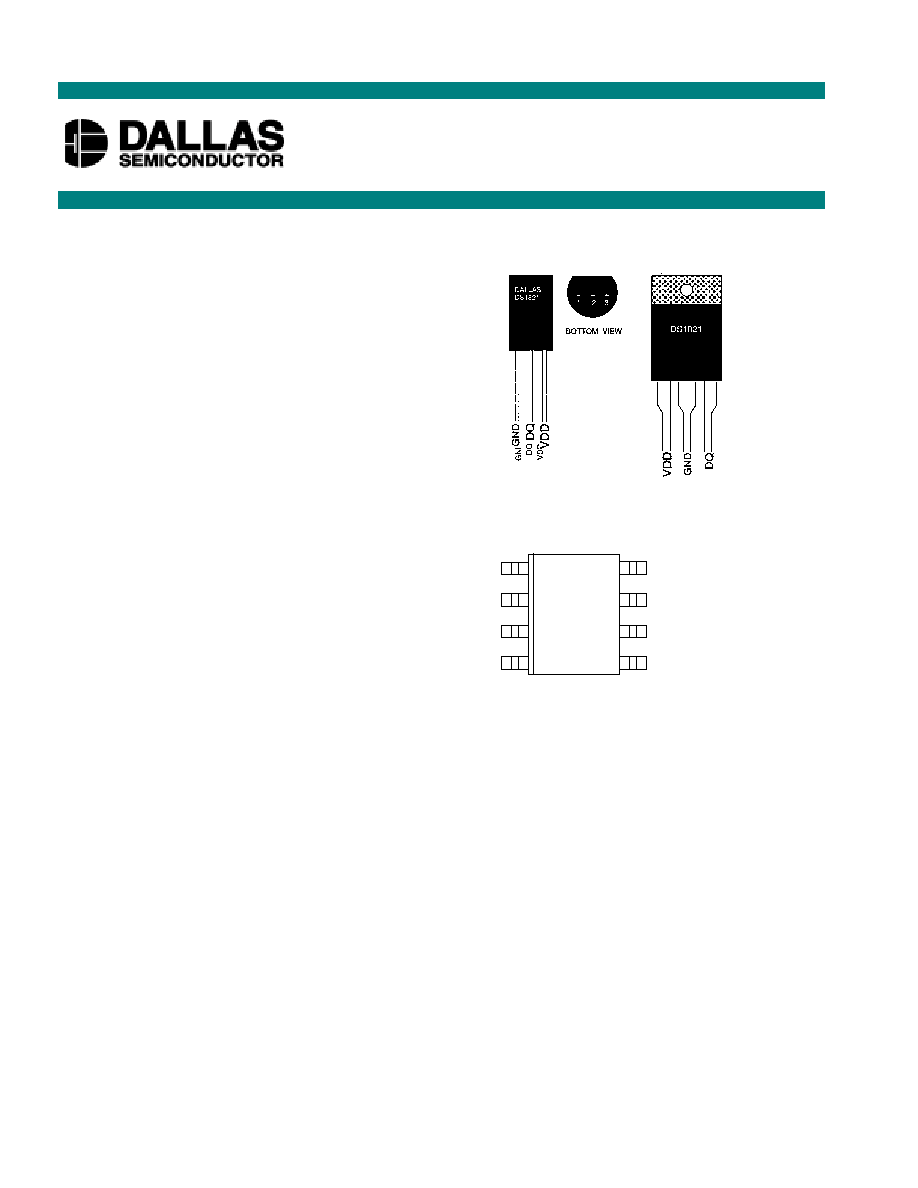
Available in 3-pin PR35, TO-220, and 8-pin
SOIC packages
Applications include thermostatic controls,
industrial systems, consumer products,
thermometers, or any thermally sensitive
system
PIN ASSIGNMENT
PIN DESCRIPTION
GND
- Ground
DQ
- Data In/Out
V
DD
- Power Supply Voltage +5V
NC
- No Connect
DNC
- Do Not Connect
DESCRIPTION
The DS1821 Programmable Digital Thermostat provides a thermal alarm logic output when the
temperature of the device exceeds a user-defined temperature TH. The output remains active until the
temperature drops below user defined temperature TL, allowing for any hysteresis necessary.
User-defined temperature settings are stored in nonvolatile memory, so parts can be programmed prior to
insertion in a system. Communication to/from the DS1821 is accomplished through the DQ pin in a
programming mode; this same pin is used in operation as the thermostat output.
DS1821
Programmable Digital Thermostat
www.dalsemi.com
6
3
1
2
4
8
7
5
DQ
GND
NC
DNC
V
DD
NC
NC
DNC
DS1821S 8-Pin SOIC (208-mil)
See Mech Drawings Section
DS1821
PR35 PACKAGE
See Mech. Drawing
Section
DS1821T
TO-220 PACKAGE
See Mech. Drawing
Section

DS1821
2 of 16
DETAILED PIN DESCRIPTION
PIN
PR35
PIN
TO-220
PIN
8-PIN
SOIC
SYMBOL
DESCRIPTION
1
2/TAB
2
GND
Ground.
2
3
1
DQ
Data input/output pin for 1-Wire
TM
programming
operation; Thermostat output pin in normal operation.
3
1
8
V
DD
V
DD
pin. +5V nominal.
DS1821S (8-pin SOIC): All pins not specified in this table are not to be connected.
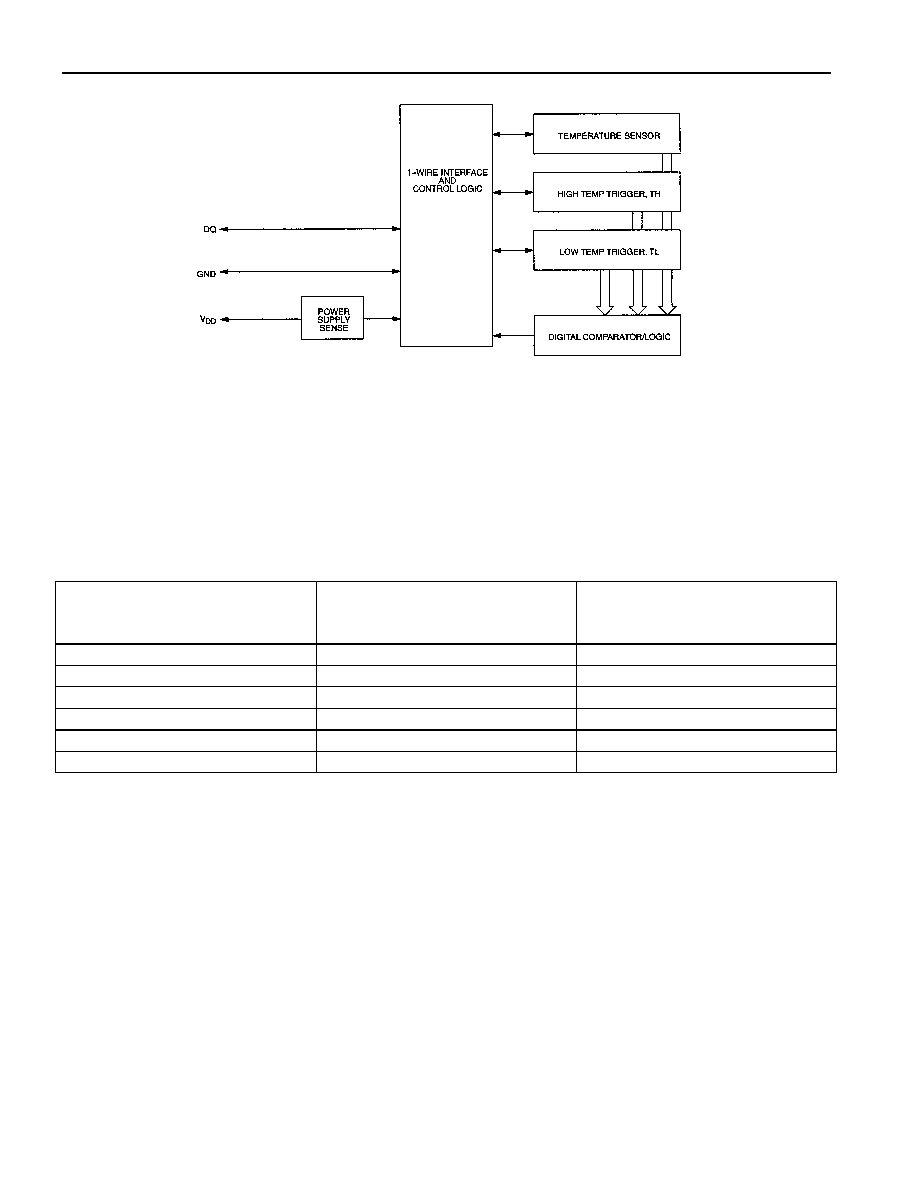
OVERVIEW
The block diagram of Figure 1 shows the major components of the DS1821. The DS1821 has two
operating modes: 1-Wire
TM
and thermostat.
The part arrives from the factory in 1-Wire mode. In this mode, the DQ pin of the DS1821 is configured
as a 1-Wire communication port which would be connected to a microprocessor. The microprocessor will
write data into the high and low temperature trigger registers, TH and TL, respectively, to set up the
temperature limits for thermostat operation. In this mode, the result of the last temperature measurement
made by the DS1821 may also be read directly by the microprocessor.
Once temperature limits have been set and thermometer operation has been verified, the user may convert
the DS1821 from a temperature sensor into a thermostat by writing to a bit in the status register. The part
will then be configured for thermostat operation; this will also become the default power-up state for the
device on the subsequent power up.
In thermostat mode, the DQ line becomes the thermostat output. This open drain output will go to its
active state (programmable on/off) when the temperature of the DS1821 goes above the limit set in the
TH register, and will remain active until the temperature goes below the limit programmed into the TL
register.
If the user wishes to establish communications with the DS1821 once it has been placed in thermostat
mode (for example, to change temperature trip point limits), this may be done by dropping V
DD
while
holding the DQ line high, then clocking the DQ line 16 times. The part will then be placed into 1-Wire
mode, and will allow the I/O functions of the device to operate, and reads from or writes to the memory
are possible. This does not change the power-up state of the device, unless the user writes the
configuration bit to do so.
DS1821
3 of 16
DS1821 BLOCK DIAGRAM Figure 1
OPERATION
Temperature Measurement
The DS1821 measures temperatures through the use of an onboard proprietary temperature measurement
technique. The temperature reading is provided in an 8-bit, two's complement reading. Table 1 describes
the exact relationship of output data to measured temperature. The data is transmitted serially over the 1-
Wire interface. The DS1821 can measure temperature over the range of -55
°
C to +125
°
C in 1
°
C
increments. For Fahrenheit usage, a lookup table or conversion factor must be used. Please refer to
Application Note 105 for the method to increase the resolution of the DS1821.
TEMPERATURE/DATA RELATIONSHIPS Table 1
TEMPERATURE
DIGITAL
OUTPUT
(Binary)
DIGITAL
OUTPUT
(Hex)
+125°C
01111101
7Dh
+25°C
00011001
19h
0°C
00000000
00h
-1°C
11111111
FFh
-25°C
11100111
E7h
-55°C
11001001
C9h

DS1821
4 of 16
Thermostat Controls
In its thermostat mode, the DS1821 functions as a thermostat with programmable hysteresis, as shown in
Figure 2. Temperature conversions begin as soon as V
DD
is applied to the device, and are continually
made, so that the thermostat output updates as soon as a temperature conversion is complete. This is
approximately once every second.
When the DS1821's temperature meets or exceeds the value stored in the high temperature trip register
(TH), the output becomes active, and will stay active until the temperature falls below the temperature
stored in the low temperature trigger register (TL). In this way, any amount of hysteresis may be
obtained.
The active state for the output is programmable by the user, so that an active state may either be a logic 1
(+5V, output transistor off) or a logic 0 (0V, output transistor on).
THERMOSTAT OUTPUT OPERATION Figure 2
DQ (Thermostat output, Active=High) V
DD
=5 volts
PROGRAMMING THE DS1821
To program the DS1821, it must be placed in 1-Wire mode. This mode is active when the device arrives
from the factory. Once the part has been programmed, and if the user has set the power-up state to
thermostat mode, 1-Wire mode may only be achieved by bringing the V
DD
pin low while holding the DQ
line high, then clocking the DQ line 16 times.
The DS1821 has four internal registers that may be accessed through the DQ pin when the device is in 1-
Wire mode. These registers are the high temperature trigger (TH), low temperature trigger (TL), the
actual measured temperature result, and the status register. The TH,TL, and status registers are all
nonvolatile.
The DS1821 must have temperature settings resident in the TH and TL registers for thermostatic
operation. The temperature result register and the thermostat limit registers (TH and TL) hold an 8-bit
number in the two's complement format described in Table 1.
TL
TH
T (°C)

DS1821
5 of 16
A status register is also present, indicating the status of the thermostatic control, and allowing
configuration of the output polarity as either active high or active low, and establishes the power-up state
of the device.
The status register is defined as follows:
where,
DONE = Conversion Done bit. 1 = Conversion complete, 0 = conversion in progress.
THF
= Temperature High Flag. This bit will normally be 0, but will be set to 1 when the temperature
exceeds the value of TH. It will remain 1 until reset by writing 0 into this location. This feature provides a
method of determining if the DS1821 has ever been subjected to temperatures above TH. This bit is
nonvolatile, and is stored in E
2
memory.
TLF
= Temperature Low Flag. This bit will normally be 0, but will be set to 1 when the temperature
is lower than the value of TL. It will remain 1 until reset by writing 0 into this location. This feature
provides a method of determining if the DS1821 has ever been subjected to temperatures below TL. This
bit is nonvolatile, and is stored in E
2
memory.
NVB
= Nonvolatile memory busy flag. 1 = Write to an E
2
memory cell in progress, 0 = nonvolatile
memory is not busy. A write to E
2
may take up to 10 ms.
T/R*
= Power-up mode bit. If set to a 1, the DS1821 will power up in a thermostat mode. If set to a
0, the device will power up in 1-Wire "read" mode. This bit is nonvolatile.
POL
= Output Polarity Bit. 1 = active high, 0 = active low. This bit is nonvolatile.
1SHOT = One-Shot Mode. If 1SHOT is 1, the DS1821 will perform one temperature conversion upon
reception of the Start Convert T protocol. If 1SHOT is 0, the DS1821 will continuously perform
temperature conversions. Note that the One-Shot mode is available only when the device is in 1-Wire
mode. In thermostat mode, the device continuously performs temperature conversions. This bit is
nonvolatile.
DONE
1
NVB
THF
TLF
T/R
POL
1SHOT