1 of 3
072799
FEATURES
§
Keeps track of hundredths of seconds,
seconds, minutes, hours, days, date of the
month, months, and years; valid leap year
compensation up to 2100
§
Watchdog timer restarts an out-of-control
processor
§
Alarm function schedules real-time related
activities
§
Programmable interrupts and square wave
outputs maintain 28-pin JEDEC footprint
§
All registers are individually addressable via
the address and data bus
§
Accuracy is better than ±2 minute/month at
25°C
§
50 bytes of user NV RAM
§
Optional 28-pin PLCC surface mount package
§
Low-power CMOS circuitry is maintained on
less than 0.5
µ
A when power is supplied from
battery input
§
Optional industrial temperature range
available on 28-pin PLCC (-40°C to +85°C)
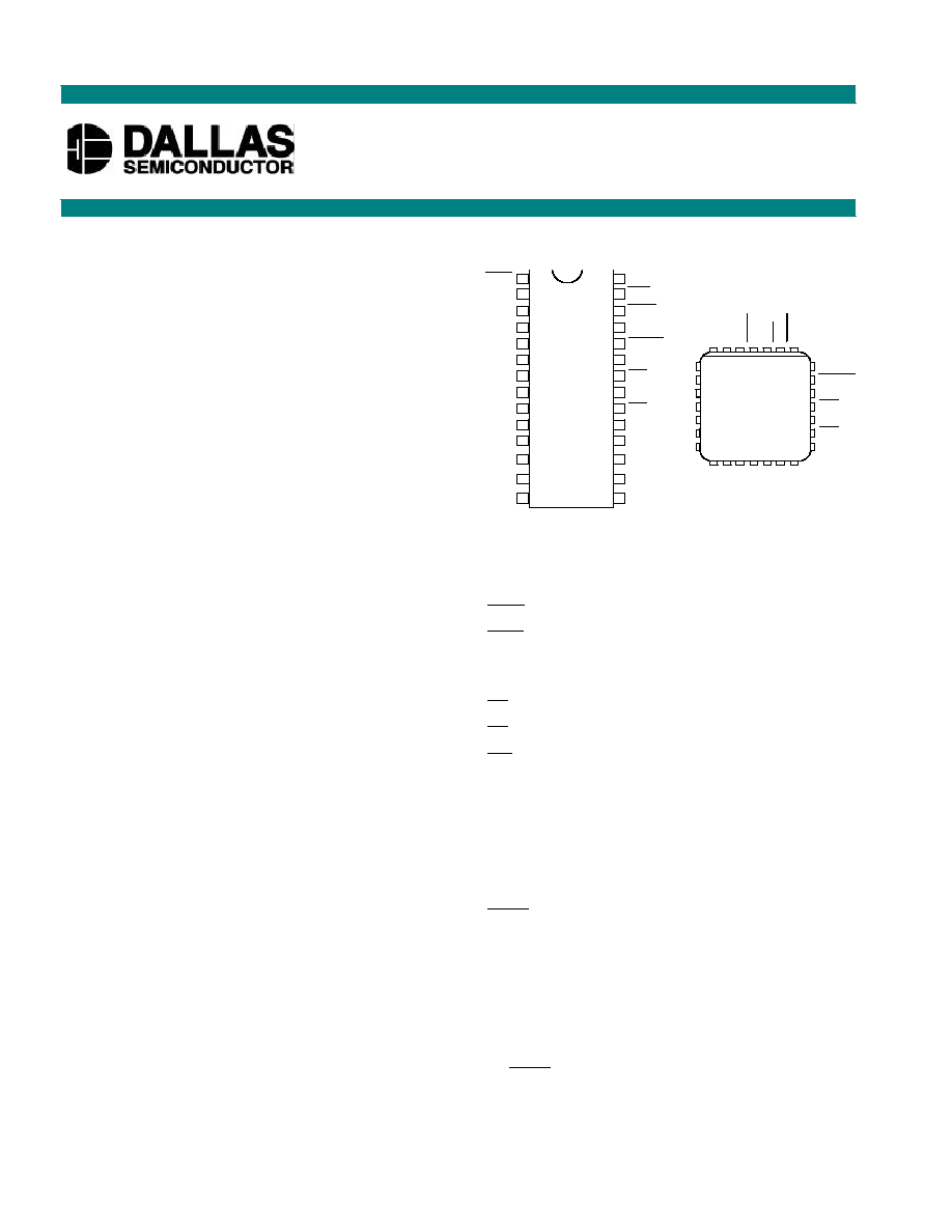
PIN ASSIGNMENT
PIN DESCRIPTION
INTA
- Interrupt Output A (open drain)
INTB
(INTB) - Interrupt Output B (open drain)
A0-A5
- Address Inputs
DQ0-DQ7
- Data Input/Output
CE
- Chip Enable
OE
- Output Enable
WE
- Write Enable
V
CC
- +5 Volts
GND
- Ground
NC
- No Connection
SQW
- Square Wave Output
X1,X2
- 32.768 kHz Crystal Connections
V
BAT
- +3 Volt Battery Input
RCLR
- RAM Clear
DESCRIPTION
The DS1284 Watchdog Timekeeper Chip is a self-contained real-time clock, alarm, watchdog timer, and
interval timer in a 28-pin JEDEC DIP package or a 28-pin PLCC surface mount package. An external
crystal and battery are the only components required to maintain time-of-day and memory status in the
absence of power. For a complete description of operating conditions, electrical characteristics, bus
timing, and pin descriptions other than X1, X2, V
BAT
, and
RCLR
, see the DS1286 Watchdog Timekeeper
data sheet.
DS1284
Watchdog Timekeeper Chip
www.dalsemi.com
DS1284
28-Pin DIP (600-mil)
DS1284
28-Pin PLCC
13
27
X2
A5
A3
A2
A1
A0
DQ0
DQ1
GND
DQ2
V
CC
INTB(INTB)
SQW
OE
GND
CE
DQ7
DQ6
DQ5
DQ3
DQ4
1
2
3
4
5
6
7
8
9
10
11
12
14
28
26
25
24
23
22
21
20
19
18
17
15
16
X1
NC
A4
INTA
A5
A4
A3
A2
A1
A0
VBAT
RCLR
SQW
OE
GND
CE
DQ0
DQ7
WE
NC X2 X1 INTA VCC WE
INTB(INTB)
DQ1 DQ2 GND DQ3 DQ4 DQ5 DQ6
25
24
23
22
21
20
19
5
6
7
8
9
10
11
4 3 2 1 28 27 26
12 13 14 15 16 17 18
V
BAT
RCLR

DS1284
2 of 3
PIN DESCRIPTION
X1, X2 - Connections for a standard 32.768 kHz quartz crystal. The internal oscillator circuitry is
designed for operation with a crystal having a specified load capacitance (C
L
) of 6 pF. The crystal is
connected directly to the X1 and X2 pins. There is no need for external capacitors or resistors. For more
information on crystal selection and crystal layout considerations, please consult Application Note 58,
"Crystal Considerations with Dallas Real Time Clocks."
V
BAT
- Battery input for any standard 3-volt lithium cell or other energy source. Battery voltage must be
held between 2.4 and 3.7 volts for proper operation. The nominal write-protect trip point voltage at which
access to registers containing time, watchdog, alarm, and RAM information is denied is set by internal
circuitry as 1.26 x V
BAT
. A maximum load of 0.5
µ
A at 25°C in the absence of power should be used to
size the external energy source. The battery should be connected directly to the V
BAT
pin. A diode must
not be placed in series with the battery to the V
BAT
pin. Furthermore, a diode is not necessary because
reverse charging current protection circuitry is provided internal to the device and has passed the
requirements of Underwriters Laboratories for UL listing. An optional ground pin is provided for
connection to battery negative. This pin should be grounded but can be left floating.
RCLR
- The
RCLR
pin is used to clear (set to logic 1) all 50 bytes of user NV RAM but does not affect
the registers involved with time, alarm, and watchdog functions. In order to clear the RAM,
RCLR
must
be forced to an input logic 0 (-0. 3 to +0.8 volts) during battery back-up mode when V
CC
is not applied.
The
RCLR
function is designed to be used via human interface (shorting to ground or by switch) and not
be driven with external buffers. This pin is internally pulled up and should be left floating when not in
use.
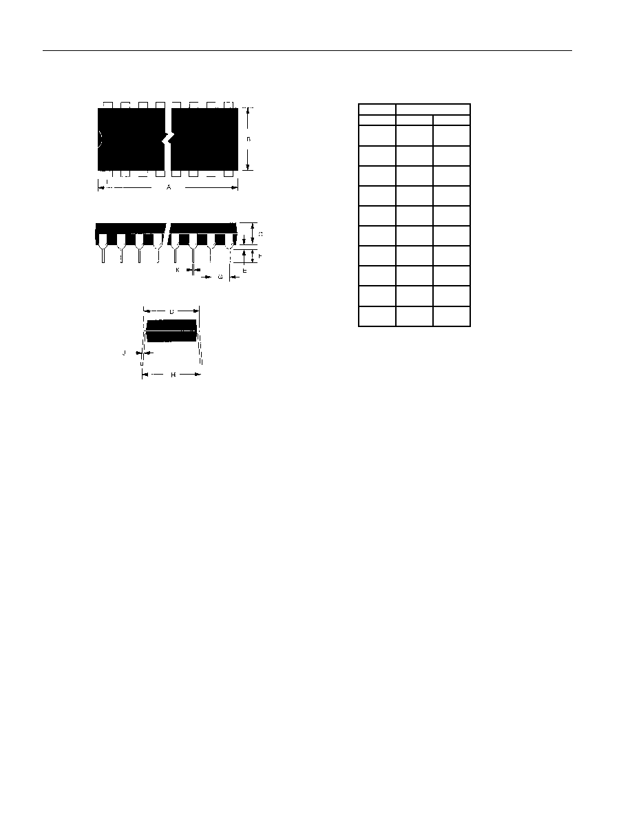
DS1284Q 28-PIN PLCC WATCHDOG TIMEKEEPER
PKG
28-PIN
DIM
MIN
MAX
A IN.
MM
0.300 BSC
7.62
B IN.
MM
0.442
17.68
0.462
11.73
D IN.
MM
0.480
12.2
0.500
12.7
D2 IN.
MM
0.390
9.91
0.430
10.92
E IN.
MM
0.090
2.29
0.120
3.05
E2 IN.
MM
0.390
9.91
0.430
10.92
F IN.
MM
0.015
0.38
0.020
0.518
H IN.
MM
0.100
2.54
0.020
0.518