Document No. 485LPCOR4300 - pg. 1/2
B&B Electronics - Revised November 2000
This product designed and manufactured in USA of domestic and imported parts by
Port-Powered RS-485 Converter
CE
Model 485LPCOR
The 485LPCOR is a port-powered two-channel RS-232 to RS-485 converter. It
converts the TD and RD RS-232 lines to balanced half-duplex RS-485 signals. The unit is
powered from the RS-232 data and handshake lines whether the lines are high or low. An
external power supply can be connected to two pins on the RS-485 connector if no
handshake lines are available. The 485LPCOR has a DB-25 female connector on the RS-
232 side and a DB-25 male connector on the RS-485 side.
RS-232 Side:
Connector: DB-25 Female.
Signals:
Passes through pins 2 (TD) and 3 (RD).
Pins 4 (RTS) and 5 (CTS) are tied together.
Pins 20 (DTR), 6 (DSR), and 8 (CD) are tied together.
RS-485 Side:
Connector: DB-25 Male.
Signals:
Half-duplex two-wire operation only.
Automatic control circuit enables driver only when transmitting.
Receiver is disabled when transmitting to prevent echo back to
RS-232 device.
Can transmit up to 4000 feet at 115.2k baud.
Power Requirements:
No external power required if two RS-232 output
handshake lines are available.
External 12VDC can be applied to pins on the RS-485 side between pins 25 (+) and 12 (GND)
if handshake lines are not available.
35mA current draw maximum under normal operation when externally powered.
NOTE: When using an external supply, the supply should be connected only to specifically labeled power inputs
(power jack, terminal block, etc.). Connecting an external power supply to the handshake lines may damage the
unit. Contact technical support for more information on connecting an external power supply to the handshake
lines.
Dimensions:
2.20" x 2.16" x 0.64" ( 5.59 x 5.49 x 1.63 cm)
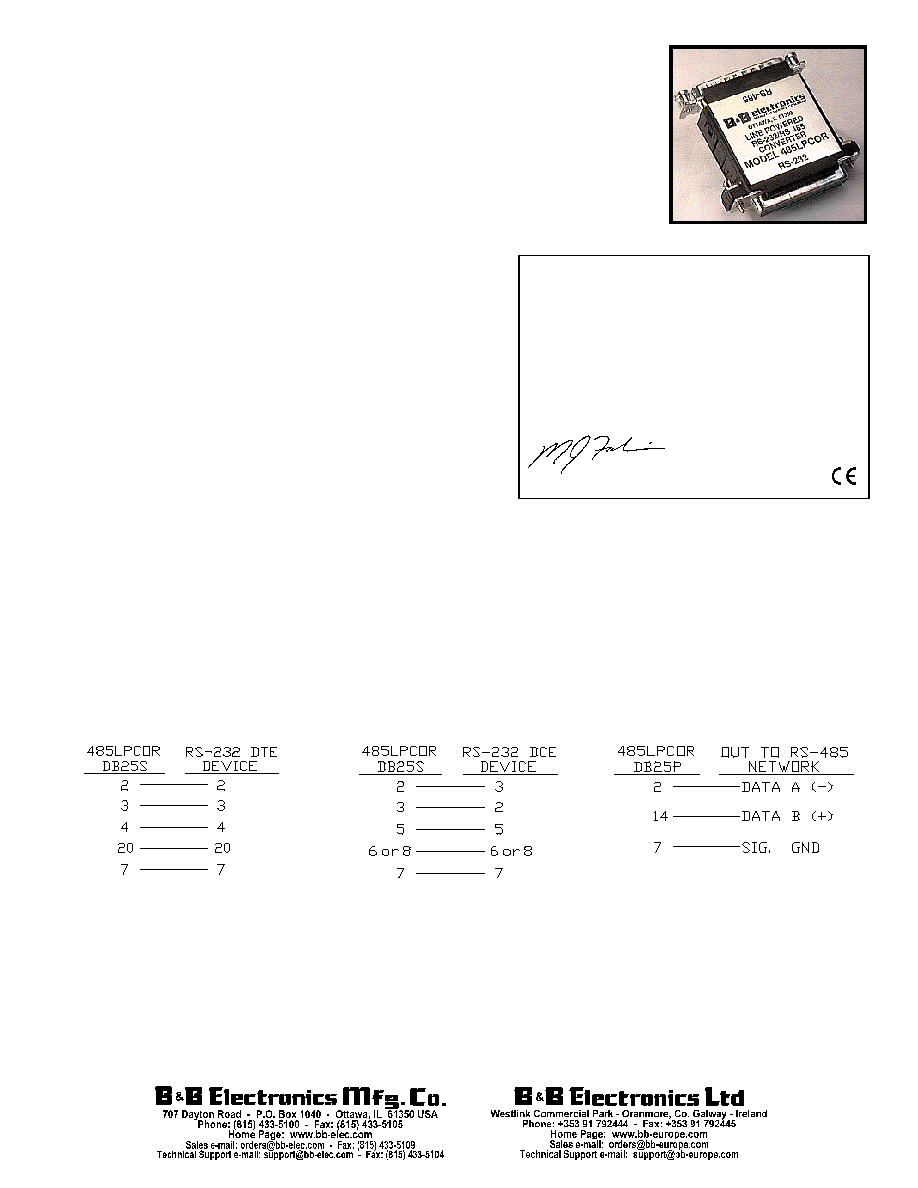
Connections and Operation:
To DB-25 RS-232 DTE device:
Can use 25 pin straight through cable.
To DB-25 RS-232 DCE device:
Can use 25 pin cable that crosses
pins 2 & 3.
To RS-485 device or network:
Pin one is also connected straight through on the 485LPCOR from the RS-232 side to the RS-485 side so that the
shield can be passed through to earth ground if desired. It is recommended that shielded cable be used and that the shield
be connected to earth ground at one point in the system. See B&B Electronics' RS-422/RS-485 Application Note for further
information on shielding.
DECLARATION OF CONFORMITY
Manufacturer's Name:
B&B Electronics Manufacturing Company
Manufacturer's Address:
P.O. Box 1040
707 Dayton Road
Ottawa, IL 61350 USA
Model Number:
485LPCOR
Description:
Port-Powered RS-485 Converter
Type:
Light industrial ITE equipment
Application of Council Directive:
89/336/EEC
Standards:
EN 50082-1 (IEC 801-2, IEC 801-3, IEC 801-4)
EN 50081-1 (EN 55022, IEC 1000-4-2)
EN 61000 (-4-2, -4-3, -4-4, -4-5, -4-6, -4-8, -4-11)
ENV 50204
EN 55024
Michael J. Fahrion, Director of Engineering
Document No. 485LPCOR4300 - pg. 2/2
B&B Electronics - Revised November 2000
This product designed and manufactured in USA of domestic and imported parts by
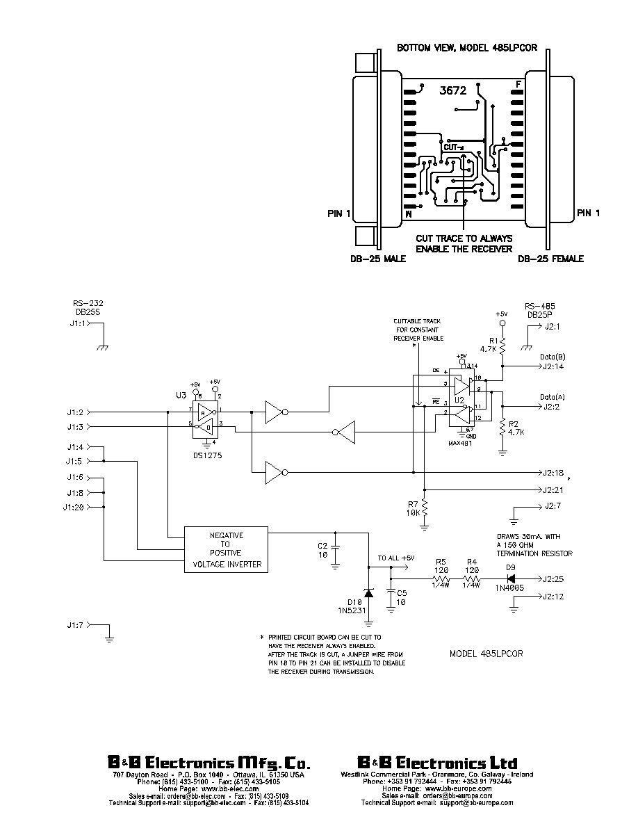
Although the 485LPCOR uses the handshake lines to
power the converter, no handshaking is required to control
the RS-485 driver. The RS-485 driver is automatically
enabled during each spacing state on the RS-232 side.
During the marking or idle state, the RS-485 driver is
disabled and the data lines are held in the marking state by
the 4.7K ohm pull-up and pull-down resistors. The value of
these resistors may need to be changed to a different value
when termination is used in order to maintain the proper DC
bias during the idle state. See B&B Electronics' RS-422/RS-
485 Application Note for more information on termination
and DC biasing of an RS-485 network.
The 485LPCOR has an internal connection to prevent
data transmitted from the RS-232 port from being echoed
back to the RS-232 port. The connection can be cut to have
the receiver always enabled. (See Figure 1.) After the
connection is cut, a jumper wire from pin 18 to pin 21 can
be installed to disable the receiver during transmission.
Figure 2
Figure 1