KSR-4023-001
1
SRC1211E
NPN Silicon Transistor
Descriptions
À
Switching application
À
Interface circuit and driver circuit application
Features
À
With built-in bias resistors
À
Simplify circuit design
À
Reduce a quantity of parts and manufacturing process
À
High packing density
Ordering
Information
Type NO.
Marking
Package Code
SRC1211E
RD
SOT-523
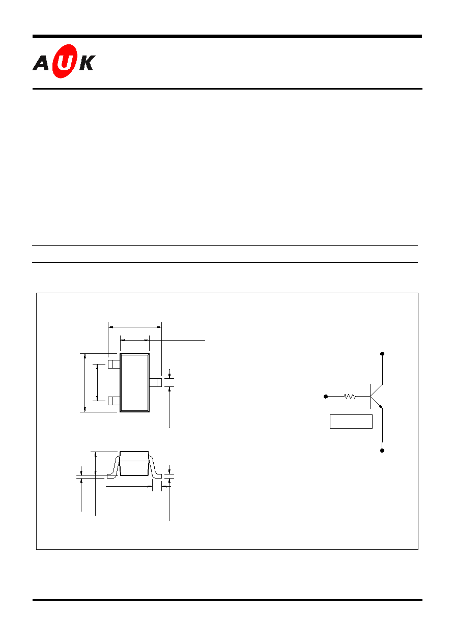
Outline Dimensions unit :
mm
S
S
e
e
m
m
i
i
c
c
o
o
n
n
d
d
u
u
c
c
t
t
o
o
r
r
À
À
À
À
Equivalent Circuit
R
1
B(IN)
E(COMMON)
C(OUT)
R
1
= 10K
PIN Connections
1.
Base
2.
Emitter
3. Collector
0.
1 M
i
n
.
1
2
3
0~
0.
1
0.
7
0
▒
0.
1
1.60
▒
0.1
.
0.80
▒
0.1
.
1.
6
0
▒
0.
1
1.
0
0
B
S
C
0.
2~
0.
3
0.15 Min.
KSR-4023-001
2
SRC1211E
Absolute maximum ratings
(Ta=25
░
░
░
░
C)
Characteristic
Symbol
Ratings
Unit
Collector-Base Voltage
V
CBO
50
V
Collector-Emitter Voltage
V
CEO
50
V
Emitter-Base Voltage
V
EBO
5
V
Collector Current
I
C
100
mA
Power Dissipation
P
D
150
mW
Junction Temperature
T
J
150
░
C
Storage Temperature
T
STG
-55 ~ 150
░
C
Electrical Characteristics
(Ta=25
░
░
░
░
C)
Characteristic
Symbol
Test Condition
Min. Typ. Max.
Unit
Collector Cut-off Current
I
CBO
V
CB
=50V, I
E
=0
-
-
500
nA
Emitter Cut-off Current
I
EBO
V
EB
=5V, I
C
=0
-
-
500
nA
DC Current Gain
h
FE
V
CE
=5V, I
C
=1mA
120
-
-
-
Collector-Emitter Saturation Voltage
V
CE(SAT)
I
C
=10mA, I
B
=0.5mA
-
0.1
0.3
V
Transition Frequency
f
T
*
V
CE
=10V, I
C
=5mA
-
250
-
MHz
Input Resistance
R
1
-
-
10
-
K
* : Characteristic of Transistor Only
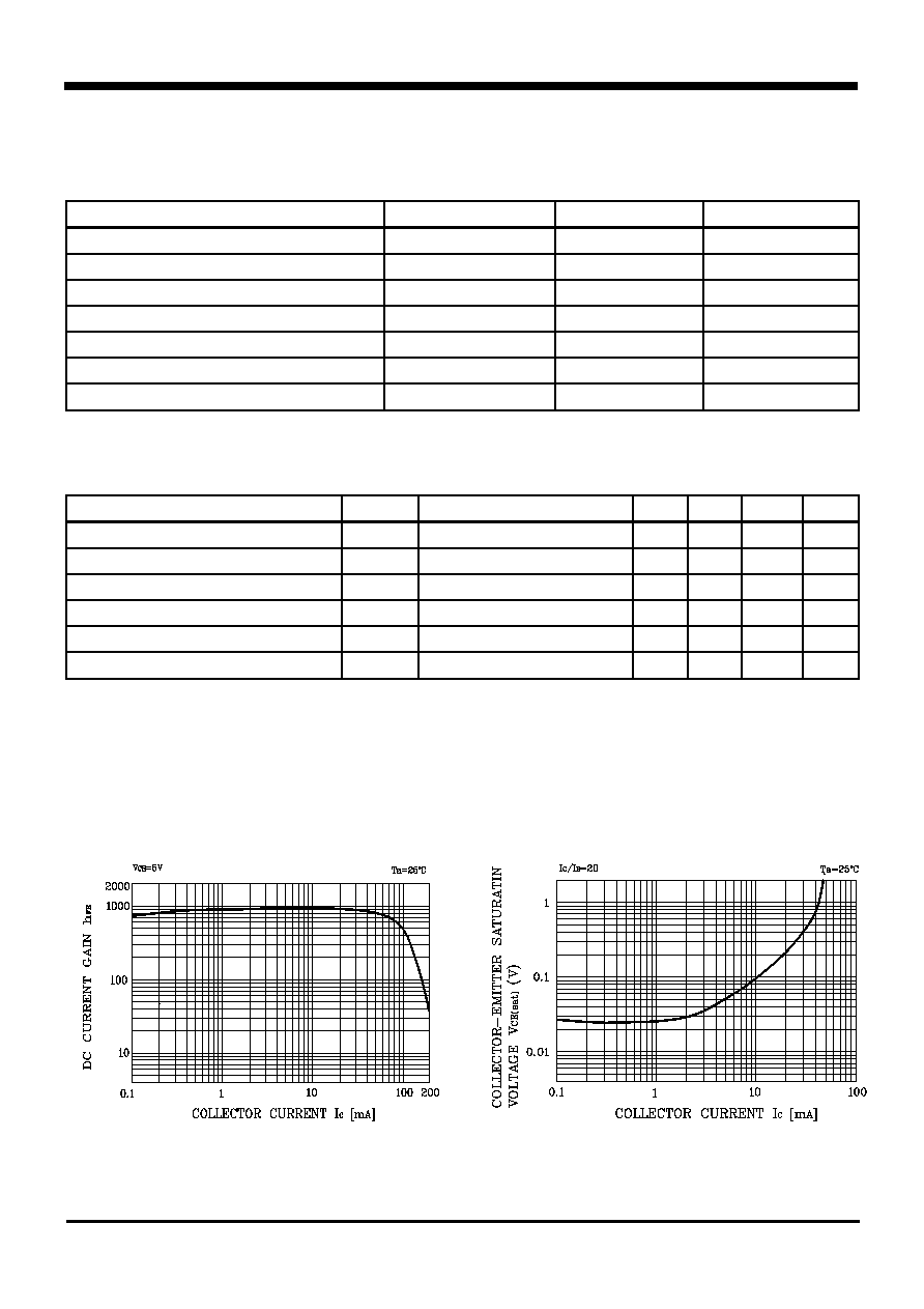
Electrical Characteristic Curves
Fig. 2 V
CE(SAT)
- I
C
Fig. 1 h
FE
- I
C