Rev. 4744ACORD09/03
Features
Speech Circuit
·
Adjustable DC Characteristic
·
Symmetrical Input of Microphone Amplifier
·
Receiving Amplifier for Dynamic or Piezo-electric Earpieces
·
Automatic Line-loss Compensation
Dialer
·
DTMF/Pulse Switchable
·
Pulse Dialing 66/33 or 60/40 or DTMF Dialing Selectable by Pin
·
Selectable Flashing Duration by Key Pad
·
Pause Function
·
Optical Indication of Temporary DTMF Mode
·
Keytone for Pulse Dialing
·
Last Number Redial up to 32 Digits
·
Three by 17 Digits Direct (One-touch) Memory
·
Ten by 17 Digits Indirect (Two-touch) Memory
·
Notice Function up to 32 Digits
·
Standard Low-cost Crystal 3.58 MHz or Ceramic Resonator
·
Handset Mute (Privacy) with Optical Indication
·
Additional Toggle Flipflop
·
Internal Loop Interrupt Detection
Tone Ringer
·
2-tone Ringer
·
Adjustable Volume
·
RC Oscillator
·
Adjustable Threshold
Benefits
·
Low Number of External Components
·
High Quality through One IC Solution
Electrostatic sensitive device.
Observe precautions for handling.
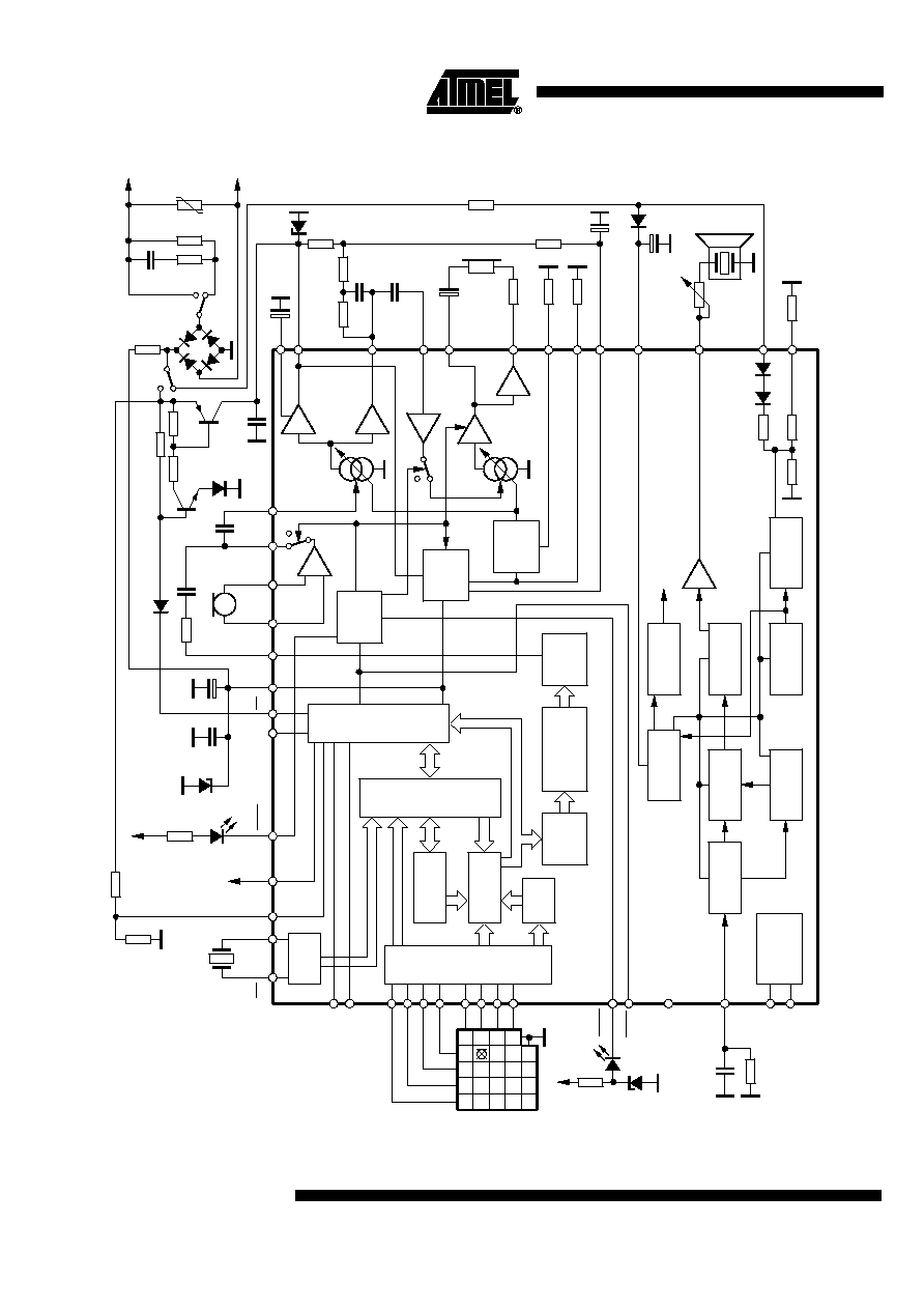
Description
Atmel's low-voltage telephone circuit U3761MB-T performs all the speech and line
interface functions required in an electronic telephone set, a tone ringer, a pulse and
DTMF dialing with redial, notice function, and 13 memories. Operation below 15 mA is
possible with reduced performance.
Universal
Telephone IC -
All Functions
Integrated
U3761MB-T

4
U3761MB-T
4744ACORD09/03
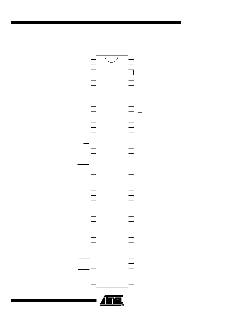
Pin Description
Pin
Symbol Function
Configuration
1
C1
Keyboard input
2
C2
3
C3
4
C4
5
Earth
Earth key (604 ms high pulse, 1 s pause)
6
HFI
Toggle flipflop input
Input with 200 k
W
pull-down resistor
HFI triggers HFO with each LOW/HIGH edge
7
HFO
Output will be toggled by each LOW/HIGH edge at HFI
C1
VDD
VDD
VDD
VDD
C2-C4
PD
PD = Protection Device
VDD
EARTH
PD
HFI
VDD
VDD
PD
2
0
0
K
HFO
VDD
PD

5
U3761MB-T
4744ACORD09/03
8
9
XT
XT
A built-in inverter provides oscillation with an inexpensive
3.579545-MHz crystal or ceramic resonator
10
MFO
Output of DTMF
DTMF output frequency
Specified (Hz) Actual (Hz) Error (%)
R
1
697
699
+0.28
R
2
770 766
-0.52
R
3
852 848
-0.47
R
4
941 940
-0.10
C
1
1209 1216
+0.57
C
2
1336 1332
-0.30
C
3
1477 1472
-0.34
11
MFIND
During the temporary DTMF mode the output switches to
low
Reset by on hook condition
Maximum voltage at MFIND = 5.5 V
12
GND
Ground
13
14
MIC 1
MIC 2
Inverting input of microphone amplifier
Non-inverting input of microphone amplifier
Pin Description
Pin
Symbol Function
Configuration
XT
VDD
VDD
VDD
VDD
XT
PD
PD
MFO
VDD
VDD
PD
VDD
MFIND
PD
MFIND
MIC2
VI
VI
MIC1
PD
PD
1 V
1 V
50K
50K