Document Outline
- Features
- Product Description
- Applications
- Typical Performances
- Color Principle
- Camera Description
- Standard Conformity
- Camera Command and Control
- Timing
- Synchronization Mode
- Output Data Timing
- Serial RGB Mode with Two Outputs: (H = 0, 6, 8; S = 0; Y = 0/1; T = 0/1)
- Serial RGB Mode with One Output (multiplexed data): (H = 1, 3, 5, 7, 9; S = 0; Y = 0/1; T = 0/1)
- Parallel RGB Mode with 1 to 1 Interpolation: (H = 1, 3, 5, 7, 9; S = 1; Y = x; T = 0/1)
- Parallel RGB Mode with 3 to 1 Interpolation: (H = 1, 3, 5, 7, 9; S = 2; Y = x; T = 0/1)
- Camera Synchronization
- Electrical Interface
- Connector Description
- Mechanical Characteristics
- Ordering Code
1
Features
Ě
High Sensitivity and High SNR Performance Linear CCD Sensor
Ě
Mono Line 1365 RGB Patterns (Total 4096 Active Pixels)
Ě
Built-in Anti-Blooming, No Lag
Ě
CameraLink Data Format (Base Configuration)
Ě
High Data Rate up to 60 Mpixels/s
Ě
Flexible and Easy to Operate via RS232 Control:
ş Gain: 0 dB to 30 dB by Step of 0.05 dB
ş Trigger Mode: Free Run or External Trigger Modes
ş Data Output Mode (Dual, Single)
Ě
Multi Camera Synchronization
Ě
Single Power Supply: DC 12V to 24V
Ě
Very Compact Design: 56 x 60 x 39.4 mm (w, h, l)
Ě
High Reliability ş CE and FCC Compliant
Ě
F (Nikon), T2 (M42 x 0.75), or M42 x 1 Mount Adapter (Lens Not Supplied)
Product Description
As part of AViiVA family, this is designed with three concepts in mind: accuracy, versa-
tility and easy implementation:
Ě
A very compact mechanical design incorporates a 4k color linear sensor.
Ě
Atmel manages the whole chain, from the sensor to the camera. The result is a
camera able to work in 8- or 12-bit, with dedicated electronics offering an
excellent signal to noise ratio.
Ě
The programmable settings let the user work at different integration time, gain and
offset. External clock and trigger allow the synchronization of several cameras.
Applications
Performance and reliability of this camera make it suitable for machine vision applica-
tions requiring low cost color capture i.e. print, packaging inspection or part sorting.
Using this camera avoids facing usual problems observed with tri-linear sensor on
optical alignment and object synchronization.
AViiVA
TM
C2 CL
4010
CameraLink
TM
Color Linescan
Camera
Preliminary
Rev. 2189CşIMAGEş04/03
2
AViiVA C2 CL 4010
2189CşIMAGEş04/03
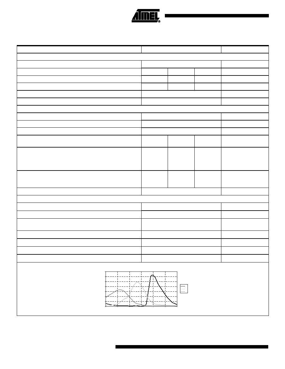
Typical Performances
Notes: 1. LSB are given for 12-bit configuration (available in serial RGB)
2. nJ/cm▓ measured on the sensor with BG38 2 mm
3. Camera front face temperature
Table 1. Typical Performances
Parameter
Value
Unit
Sensor Characteristics at Maximum Pixel Rate
Resolution
1365 RGB patterns or 4096 pixels
pixels
Pixel dimensions
Blue
Green
Red
ş
Pixel size
7 x 19.8
7 x 20
7 x 17.4
Ám▓
Pixel pitch
10
10
10
Ám
Max Line rate
14
kHz
Anti blooming
x 150
ş
Radiometric Performances (maximum Pixel Rate, Tamb = 25░C)
Dynamic range
8 ş 12
bit
Spectral range
250 ş 1100
nm
Linearity
< 1
%
Gain range (step of 0.047 dB)
Gmin
0
Gnom
18
Gmax
30
dB
Peak response
(1)(2)
Blue
Green
Red
16.6
24.2
31.3
132.8
193.6
250.4
1062.4
1548.8
2003.2
LSB/(nJ/cm
2
)
LSB/(nJ/cm
2
)
LSB/(nJ/cm
2
)
Output RMS noise
SNR
Effective bit
67.4
11.2
49
8.2
37
6.2
dB
bit
PRNU (Photo Response Non Uniformity
▒ 4 (▒ 15 max)
%
Mechanical and Electrical Interface
Size (w x h x l)
56 x 60 x 39.4
mm
Lens mount
F, T2, M42 x 1
ş
Sensor alignment (See "Sensor Alignment" on page 19)
x,y = ▒50 ş
z = ▒30 ş
tilt
z
= 0-35
x,y = ▒0.2
Ám
░
Power supply
DC, single 12 to 24
V
Power dissipation
< 7
W
Operating temperature
(3)
0 to 65 (non condensing)
░
C
Storage temperature
-40 to 75 (non condensing)
░
C
Spectral Response
(1)
(2)
0
5
10
15
20
25
30
35
400
450
500
550
600
650
700
Responsivity LSB/(nJ/cm▓)
Wavelength (nm)
R
G
B
3
AViiVA C2 CL 4010
2189CşIMAGEş04/03
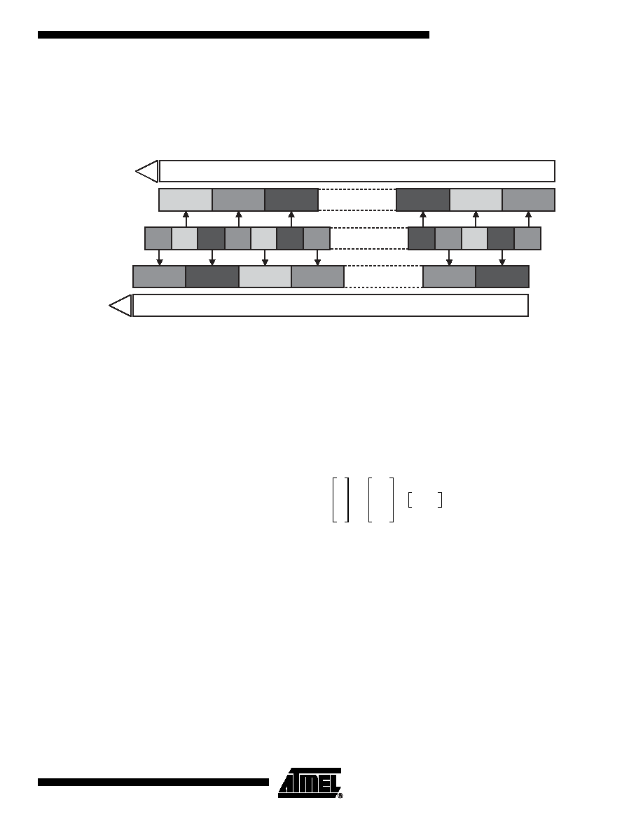
Color Principle
CCD Description
The color CCD sensor is based on a 2 taps, 4096 pixels linear sensor with RGB color filter. It
results 1365 RGB patterns (+1 extra red pixel).
Figure 1. Color CCD Sensor Synoptic
IR Cut-Off Filter
For calibrated color response, the AViiVA C2 sensor shall not be exposed to IR wavelength
(> 700 nm). Therefore depending of the ligth source, the user shall place or not a IR cut-off fil-
ter in front of the sensor. The AViiVA C2 sensor has been calibrated with a BG38 2 mm. The
AViiVA C2 is available with or without BG38 2 mm (refer to the ordering code).
White Balance
The white balance function is not included in the camera. It shall be done by software or hard-
ware at application level.
The color filters are balanced for a typical 5500
░
K light source with BG38 2 mm. For each light
source, the white balance shall be done. For example, at 3200
░
K with GB38 2 mm,the follow-
ing typical gains must be applied to white balance the images.
Color Space
Correction
The color space correction function is not included in the camera. It shall be done by software
or hardware at application level.
After white balance, the color space correction shall be done to improved the color response.
This correction consists in a linear operation to convert the RGB triplet form the camera color
space to the RGB triplet of the final color space. The final color space can be a monitor, a
printer or others application specific color space. For some specific applications where "abso-
lute" color value is not mandatory the color space correction can by bypassed.
At 3200K with BG38 2 mm and for a standard PC screen, this typical matrix must be applied to
correct the colors.
G1
R1
B1
R2
G2
B2
B1364 R1365
G1365
B1365 R1366
R3
RGB color pixels
R1
G1
B1
G2
R1
R2
B2
B1364
G1365
R1366
R1365
B1365
Storage area
Storage area
EVEN pixels CCD shift register
ODD pixels CCD shift register
VOS1
VOS2
5
*
%
1
1.64
2.89
5 * %
Î
=
4
AViiVA C2 CL 4010
2189CşIMAGEş04/03
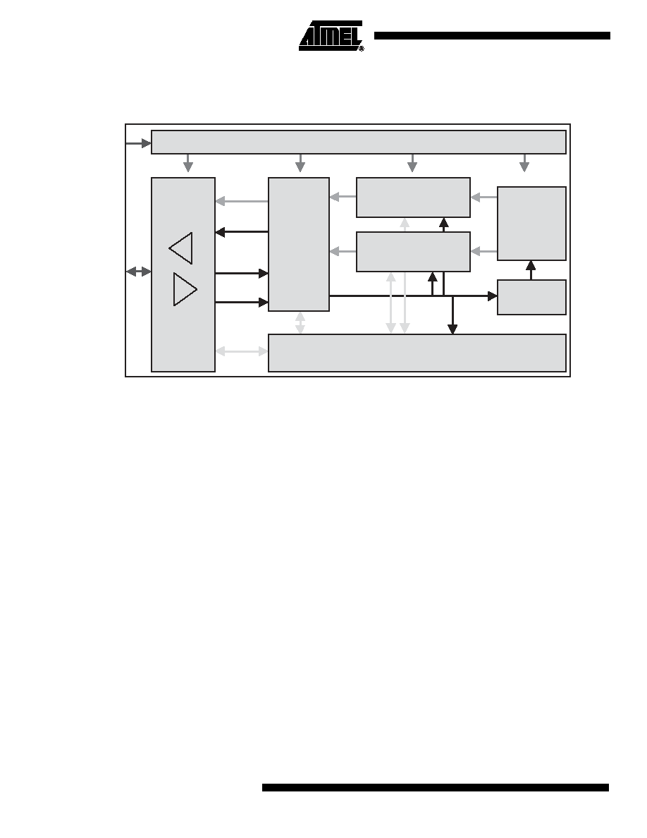
Camera Description
Figure 2. Camera Synoptic
The camera is based on a two-tap linear CCD. Therefore, two analog chains process odd and
even pixel outputs of the linear sensor. The CCD signal processing encompasses the corre-
lated double sampling (CDS), the dark level correction (dark pixel clamping), the gain (PGA)
and offset correction and finally the analog to digital conversion on 12-bit.
Note:
PGA stands for Programmable Gain Array.
The camera is powered by a single DC power supply from 12V to 24V.
The functional interface (data and control) is provided with the CameraLink interface. The
camera uses the base configuration of CameraLink standard.
Note:
FVAL = 0
In RGB serial mode, the data can be delivered eitheir on two channels or on a single multi-
plexed channel. The data format can be configured in 8-or 12-bit, See "Output Data Timing" on
page 9.
In RGB parallel mode, the data are provided on three channels corresponding to red, green
and blue information. The data format is only on 8-bit. In this mode two interpolation mecha-
nism can be selected, See "Output Data Timing" on page 9.
The camera can be used with external triggers (TRIG1 and TRIG2 signals) in different trigger
modes (see "Synchronization Mode" on page 7). The camera can be also clocked externally,
allowing system synchronization and/or multi-camera synchronization.
The camera configuration and settings are performed via a serial line.
This interface is used for:
Ě
Gain, offset setting.
Ě
Dynamic range, data rate setting, RGB mode.
Ě
Trigger mode setting: free run or external trigger modes.
Ě
Integration time setting: in free running and external trigger mode.
Linear CCD
2 taps
CCD Drivers
Even pixels analog chain
PGA, CDS, ADC
12-bit at 30 Mpixels/s
Odd pixels analog chain
PGA, CDS, ADC
12-bit at 30 Mpixels/s
Microcontroller
CameraLink
transceiver
TX
RX
Power supplies
DC power
CameraLink
I/F
Sequencer
controller
DATA
Serial line
TRIG1,
TRIG2
STROBE,
LVAL
CLOCK_IN

5
AViiVA C2 CL 4010
2189CşIMAGEş04/03
Standard
Conformity
The cameras have been tested in the following conditions:
Ě
Shielded power supply cable.
Ě
CameraLink data transfer cable ref. 14B26-SZLB-500-OLC (3M).
Ě
Linear AC-DC power supply.
Atmel recommends using the same configuration to ensure the compliance with the following
standards.
CE Conformity
AViiVA Cameras comply with the requirements of the EMC (European) directive 89/336/CEE
(EN 50081-2, EN 61000-6-2)
FCC Conformity
AViiVA Cameras comply with Part 15 of FCC rules.
Operation is subject to the following two conditions:
Ě
This device may not cause harmful interference, and
Ě
This device must accept any interference received, including interference that may cause
undesired operation.
This equipment has been tested and found to comply with the limits for a Class A digital
device, pursuant to part 15 of the FCC Rules. These limits are designed to provide reasonable
protection against harmful interference when the equipment is operated in a commercial envi-
ronment. This equipment generates, uses, and can radiate radio frequency energy and, if not
installed and used in accordance with the instruction manual, may cause harmful interference
to radio communications. Operation of this equipment in a residential area is likely to cause
harmful interference in which case the user will be required to correct the interference at his
own expense.
Warning: Changes or modifications to this unit not expressly approved by the party responsi-
ble for compliance could void the user's authority to operate this equipment.
Camera
Command and
Control
Camera configuration is set through the serial interface. Please refer to "Serial Communica-
tion" on page 15 for the detailed protocol of the serial line.