
1
Features
Ę
Advanced, High-speed, Electrically-erasable Programmable Logic Device
Ł Superset of 22V10
Ł Enhanced Logic Flexibility
Ł Backward Compatible with ATV750B/BL and ATV750/L
Ę
Low-power Edge-sensing "L" Option with 1 mA Standby Current
Ę
D- or T-type Flip-flop
Ę
Product Term or Direct Input Pin Clocking
Ę
7.5 ns Maximum Pin-to-pin Delay with 5V Operation
Ę
Highest Density Programmable Logic Available in 24-pin Package
Ł Advanced Electrically-erasable Technology
Ł Reprogrammable
Ł 100% Tested
Ę
Increased Logic Flexibility
Ł 42 Array Inputs, 20 Sum Terms and 20 Flip-flops
Ę
Enhanced Output Logic Flexibility
Ł All 20 Flip-flops Feed Back Internally
Ł 10 Flip-flops are also Available as Outputs
Ę
Programmable Pin-keeper Circuits
Ę
Dual-in-line and Surface Mount Package in Standard Pinouts
Ę
Commercial and Industrial Temperature Ranges
Ę
20-year Data Retention
Ę
2000V ESD Protection
Ę
1000 Erase/Write Cycles
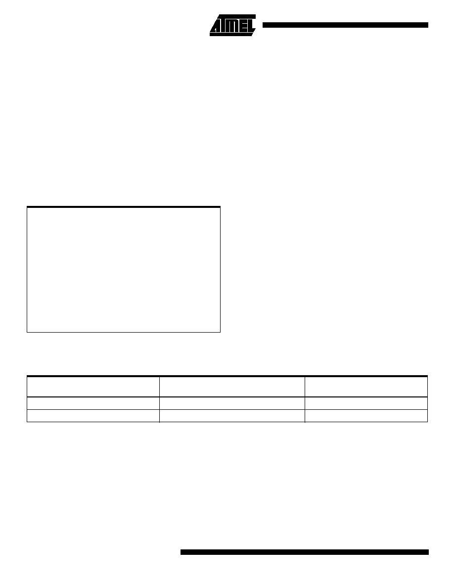
Block Diagram
Description
The ATF750C(L)s are twice as powerful as most other 24-pin programmable logic
devices. Increased product terms, sum terms, flip-flops and output logic configurations
translate into more usable gates. High-speed logic and uniform, predictable delays
PROGRAMMABLE
INTERCONNECT
AND
COMBINATORIAL
LOGIC ARRAY
LOGIC
OPTION
(UP T0 20
FLIP-FLOPS)
OUTPUT
OPTION
4 TO 8
PRODUCT
TERMS
(OE PRODUCT TERMS)
10
I/O
PINS
12
INPUT
PINS
(CLOCK PIN)
Rev. 0776FŁ01/00
High-speed
Complex
Programmable
Logic Device
ATF750C
ATF750CL
Pin Configurations
Pin Name
Function
CLK
Clock
IN
Logic Inputs
I/O
Bi-directional Buffers
*
No Internal Connection
VCC
+5V Supply
(continued)
DIP/SOIC/TSSOP
1
2
3
4
5
6
7
8
9
10
11
12
24
23
22
21
20
19
18
17
16
15
14
13
CLK/IN
IN
IN
IN
IN
IN
IN
IN
IN
IN
IN
GND
VCC
I/O
I/O
I/O
I/O
I/O
I/O
I/O
I/O
I/O
I/O
IN
PLCC
5
6
7
8
9
10
11
25
24
23
22
21
20
19
IN
IN
IN
*
IN
IN
IN
I/O
I/O
I/O
*
I/O
I/O
I/O
4
3
2
1
28
27
26
12
13
14
15
16
17
18
IN
IN
GND
*
IN
I/O
I/O
IN
IN
CLK/IN
*
VCC
I/O
I/O
ATF750C(L)
2
guarantee fast in-system performance. The ATF750C(L) is
a high-performance CMOS (electrically-erasable) complex
programmable logic device (CPLD) that utilizes Atmel's
proven electrically-erasable technology.
Each of the ATF750C(L)'s 22 logic pins can be used as an
input. Ten of these can be used as inputs, outputs or bi-
directional I/O pins. Each flip-flop is individually config-
urable as either D- or T-type. Each flip-flop output is fed
back into the array independently. This allows burying of all
the sum terms and flip-flops.
There are 171 total product terms available. There are two
sum terms per output, providing added flexibility. A variable
format is used to assign between four to eight product
terms per sum term. Much more logic can be replaced by
this device than by any other 24-pin PLD. With 20 sum
terms and flip-flops, complex state machines are easily
implemented with logic to spare.
Product terms provide individual clocks and asynchronous
resets for each flip-flop. Each flip-flop may also be individu-
ally configured to have direct input pin controlled clocking.
Each output has its own enable product term. One product
term provides a common synchronous preset for all flip-
flops. Register preload functions are provided to simplify
testing. All registers automatically reset upon power-up.
The ATF750C(L) is a low-power device with speeds
as fast as 15 ns. The ATF750C(L) provides the optimum
low-power CPLD solution. This device significantly
reduces total system power, thereby allowing battery-
powered operations.
DC and AC Operating Conditions
All members of the family are specified to operate in either one of two voltage ranges. Parameters are specified as noted to
be either 2.7V to 3.6V, 5V ▒ 5% or 5V ▒ 10%.
Absolute Maximum Ratings*
Temperature Under Bias................................ -55░C to +125░C
*NOTICE:
Stresses beyond those listed under "Absolute
Maximum Ratings" may cause permanent dam-
age to the device. This is a stress rating only and
functional operation of the device at these or any
other conditions beyond those indicated in the
operational sections of this specification is not
implied. Exposure to absolute maximum rating
conditions for extended periods may affect device
reliability.
Note:
1.
Minimum voltage is -0.6V DC, which may under-
shoot to -2.0V for pulses of less than 20 ns. Max-
imum output pin voltage is V
CC
+ 0.75V DC,
which may overshoot to 7.0V for pulses of less
than 20 ns.
Storage Temperature ..................................... -65░C to +150░C
Voltage on Any Pin with
Respect to Ground .........................................-2.0V to +7.0V
(1)
Voltage on Input Pins
with Respect to Ground
During Programming.....................................-2.0V to +14.0V
(1)
Programming Voltage with
Respect to Ground .......................................-2.0V to +14.0V
(1)
5V Operation
Commercial
-7.5, -10, -15
Industrial
-10, -15
Operating Temperature (Ambient)
0░C - 70░C
-40░C - +85░C
V
CC
Power Supply
5V
▒
5%
5V
▒
10%
ATF750C(L)
4
Bus-friendly Pin-keeper Input and I/Os
All input and I/O pins on the ATF750C(L) have programma-
ble "pin-keeper" circuits. If activated, when any pin is driven
high or low and then subsequently left floating, it will stay at
that previous high or low level.
This circuitry prevents unused input and I/O lines from
floating to intermediate voltage levels, which causes
unnecessary power consumption and system noise. The
keeper circuits eliminate the need for external pull-up resis-
tors and eliminate their DC power consumption.
Enabling or disabling of the pin-keeper circuits is controlled
by the device type chosen in the logic compiler device
selection menu. Please refer to the software compiler table
for more details. Once the pin-keeper circuits are disabled,
normal termination procedures are required for unused
inputs and I/Os.
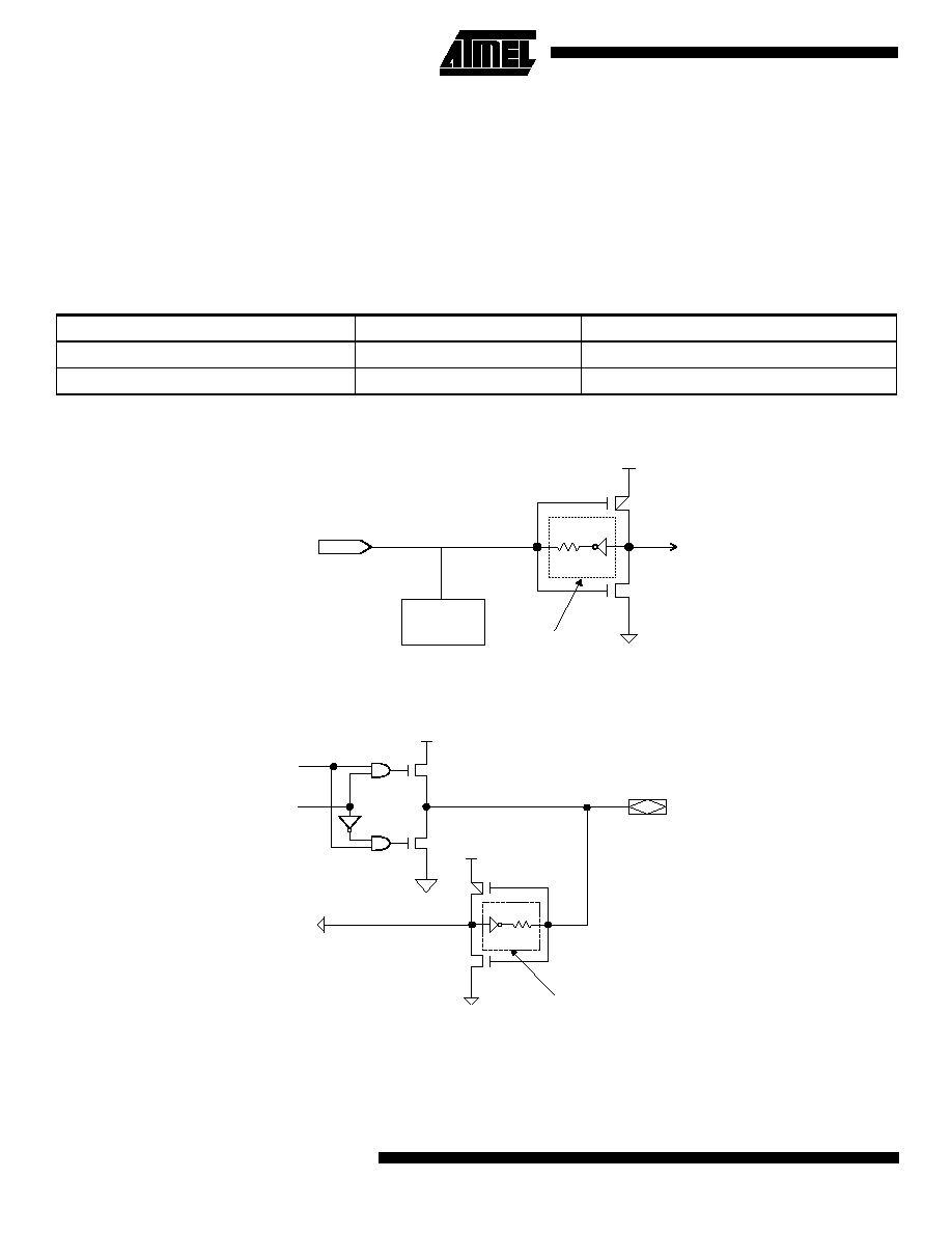
Input Diagram
I/O Diagram
Table 1. Software Compiler Mode Selection
Synario
WINCUPL
Pin-keeper Circuit
ATF750C
V750C
Disabled
ATF750C (PPK)
V750CPPK
Enabled
100K
V
CC
ESD
PROTECTION
CIRCUIT
INPUT
PROGRAMMABLE
OPTION
100K
V
CC
V
CC
DATA
OE
I/O
PROGRAMMABLE
OPTION
ATF750C(L)
5
Note:
1. Not more than one output at a time should be shorted. Duration of short circuit test should not exceed 30 sec.
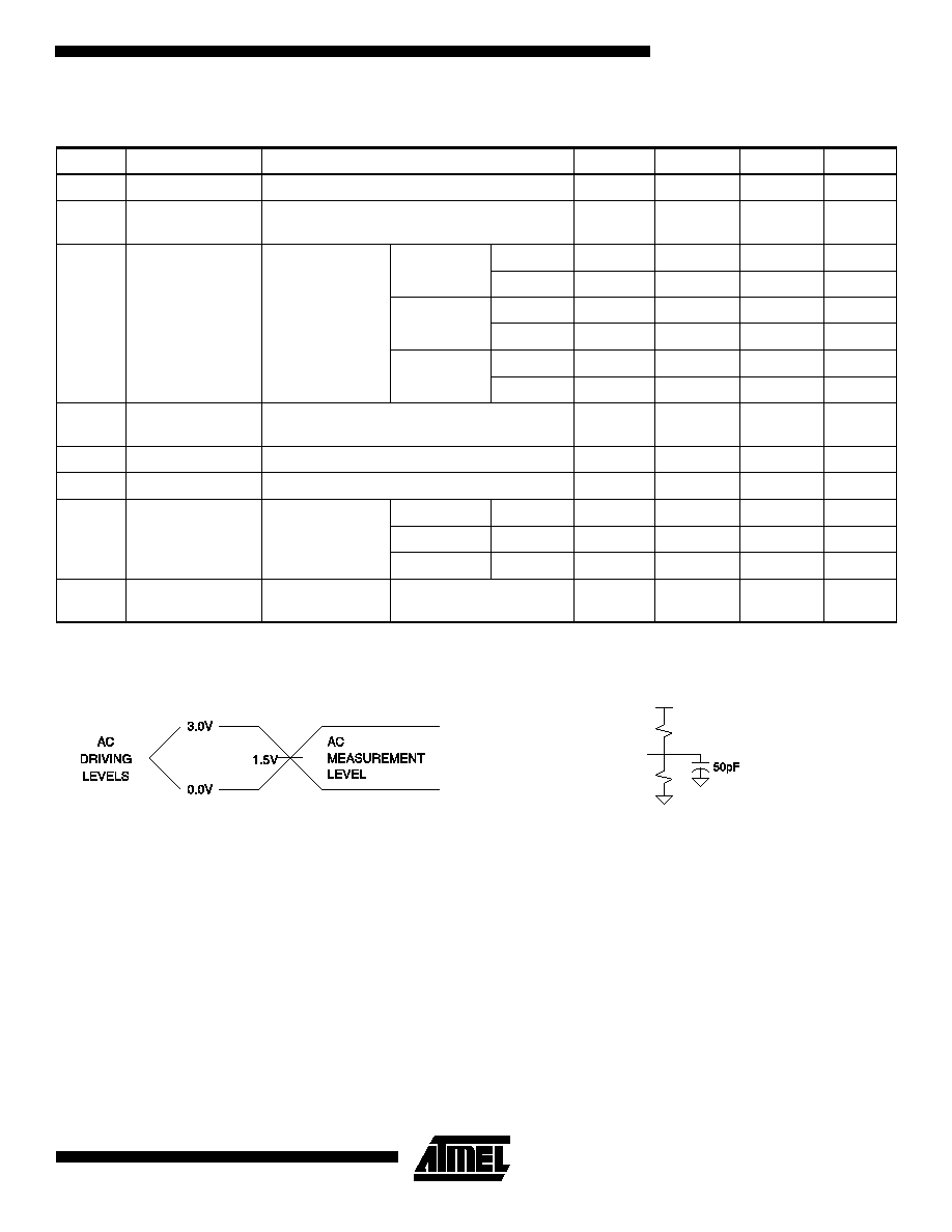
Input Test Waveforms and
Measurement Levels
t
R
, t
F
< 3 ns (10% to 90%)
Output Test Load
DC Characteristics
Symbol
Parameter
Condition
Min
Typ
Max
Units
I
LI
Input Load Current
V
IN
= -0.1V to V
CC
+ 1V
10
ĄA
I
LO
Output Leakage
Current
V
OUT
= -0.1V to V
CC
+ 0.1V
10
ĄA
I
CC
Power Supply
Current, Standby
V
CC
= Max,
V
IN
= Max,
Outputs Open
C-7, -10
Com.
125
180
mA
Ind., Mil.
135
190
mA
C-15
Com.
125
180
mA
Ind., Mil.
135
190
mA
CL-15
Com.
0.12
1
mA
Ind., Mil.
0.15
2
mA
I
OS
(1)
Output Short
Circuit Current
V
OUT
= 0.5V
-120
mA
V
IL
Input Low Voltage
4.5
V
CC
5.5V
-0.6
0.8
V
V
IH
Input High Voltage
2.0
V
CC
+ 0.75
V
V
OL
Output Low
Voltage
V
IN
= V
IH
or V
IL
,
V
CC
= Min
I
OL
= 16 mA
Com., Ind.
0.5
V
I
OL
= 12 mA
Mil.
0.5
V
I
OL
= 24 mA
Com.
0.8
V
V
OH
Output High
Voltage
V
IN
= V
IH
or V
IL
,
V
CC
= Min
I
OH
= -4.0 mA
2.4
V
VCC
390
(750 MIL.)
300
(390 MIL.)
