1
4241BşMP3ş07/04
Features
Ě
Protocol
ş UART Used as a Physical Layer
ş Based on the Intel Hex-type Records
ş Autobaud
Ě
In-System Programming
ş Read/Write Flash Memory
ş Read Device IDs
ş Block Erase
ş Full-chip Erase
ş Read/Write Configuration Bytes
ş Security Setting From ISP Command
ş Remote Application Start Command
Ě
In-Application Programming/Self-Programming
ş Read/Write Flash Memory
ş Read Device IDs
ş Block Erase
ş Read/Write Configuration Bytes
ş Bootloader Start
Description
This document describes the UART bootloader functionalities as well as the serial
protocol to efficiently perform operations on the on-chip Flash memory. Additional
information for the AT89C51SND1 product can be found in the AT89C51SND1 data
sheet and the AT89C51SND1 errata sheet available on the Atmel web site,
www.atmel.com.
The bootloader software package (source code and binary) currently used for produc-
tion is available from the Atmel web site.
Bootloader Revision
Purpose of Modifications
Date
Revision 1.0.0
New release increasing programming
speed
June 2002
Revision 1.1.0
Bug fix in boot process
October 2002
MP3
Microcontrollers
AT89C51SND1
UART
Bootloader
2
AT89C51SND1 UART Bootloader
4241BşMP3ş07/04
Functional
Description
The AT89C51SND1 bootloader facilitates In-System Programming and In-Application
Programming.
In-System Programming
Capability
In-System Programming (ISP) allows the user to program or reprogram a microcontrol-
ler's on-chip Flash memory without removing it from the system and without the need of
a pre-programmed application.
The UART bootloader can manage a communication with a host through the serial net-
work. It can also access and perform requested operations on the on-chip Flash
memory.
In-Application
Programming or Self-
Programming Capability
In-Application Programming (IAP) allows the reprogramming of a microcontroller's on-
chip Flash memory without removing it from the system and while the embedded appli-
cation is running.
The UART bootloader contains some Application Programming Interface routines
named API routines allowing IAP by using the user's firmware.
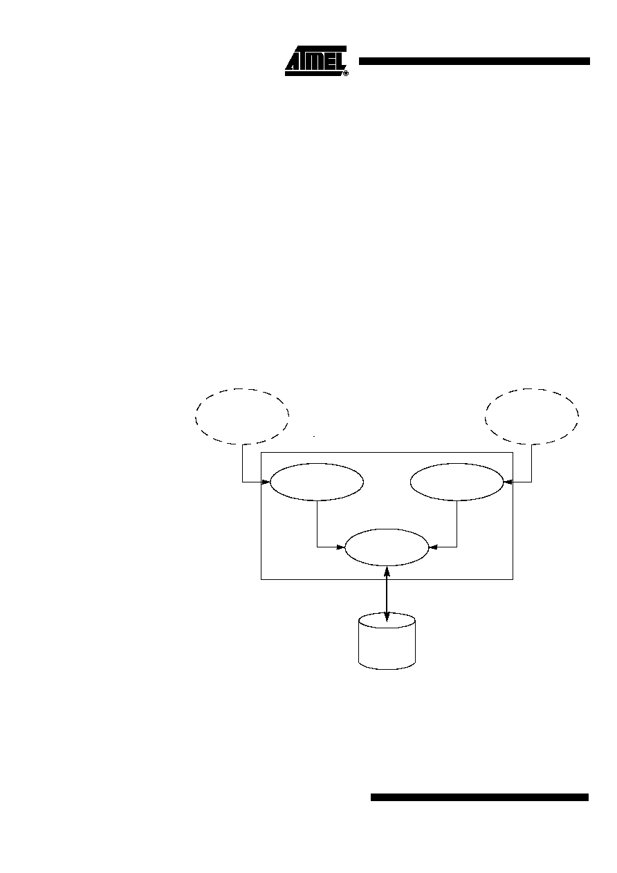
Block Diagram
This section describes the different parts of the bootloader. Figure 1 shows the on-chip
bootloader and IAP processes.
Figure 1. Bootloader Process Description
User
Application
On-chip
IAP
Management
User Call
ISP Communication
Management
UART Protocol
Communication
Management
Flash
Memory
External Host via the
Flash memory

3
AT89C51SND1 UART Bootloader
4241BşMP3ş07/04
ISP Communication
Management
The purpose of this process is to manage the communication and its protocol between
the on-chip bootloader and an external device (host). The on-chip bootloader imple-
ments a serial protocol (see Section "Protocol", page 9). This process translates serial
communication frames (UART) into Flash memory accesses (read, write, erase, etc.).
User Call Management
Several Application Program Interface (API) calls are available to the application pro-
gram to selectively erase and program Flash pages. All calls are made through a
common interface (API calls) included in the bootloader. The purpose of this process is
to translate the application request into internal Flash memory operations.
Flash Memory Management
This process manages low level accesses to the Flash memory (performs read and
write accesses).
Bootloader
Configuration
Configuration and
Manufacturer Information
The table below lists configuration and manufacturer byte information used by the boot-
loader. This information can be accessed through a set of API or ISP commands.
Mapping and Default Value of
Hardware Security Byte
The 4 Most Significant Bytes (MSB) of the Hardware Byte can be read/written by soft-
ware (this area is called Fuse bits). The 4 Least Significant Bytes (LSB) can only be
read by software and written by hardware in parallel mode (with parallel programmer
devices).
Note:
U: Unprogrammed = 1, P: Program = 0
Table 1. Configuration and Munfacturer Byte Information
Mnemonic
Description
Default Value
BSB
Boot Status Byte
FFh
SBV
Software Boot Vector
F0h
SSB
Software Security Byte
FCh
Manufacturer
58h
ID1: Family code
D7h
ID2: Product Name
ECh
ID3: Product Revision
FFh
Table 2. Mapping and Default Value of HSB
Bit Position
Mnemonic
Default Value
Description
7
X2B
U
To start in x1 mode
6
BLJB
P
To map the boot area in code area between F000h-
FFFFh
5
Reserved
U
4
Reserved
U
3
Reserved
U
2
LB2
P
To lock the chip (see datasheet)
1
LB1
U
0
LB0
U

4
AT89C51SND1 UART Bootloader
4241BşMP3ş07/04
Software Security Byte
The bootloader has Software Security Byte (SSB) to protect itself from user access or
ISP access.
The Software Security Byte (SSB) protects from ISP accesses. The command "Program
Software Security Bit" can only write a higher priority level. There are three levels of
security:
Ě
level 0: NO_SECURITY (FFh)
From level 0, one can write level 1 or level 2.
Ě
level 1: WRITE_SECURITY (FEh)
In this level it is impossible to write in the Flash memory, BSB and SBV.
The bootloader returns an error message.
From level 1, one can write only level 2.
Ě
level 2: RD_WR_SECURITY (FCh)
This is the default level.
Level 2 forbids all read and write accesses to/from the Flash memory.
The bootloader returns an error message.
Only a full-chip erase command can reset the software security bits.
Software Boot Vector
The Software Boot Vector (SBV) forces the execution of a user bootloader starting at
address [SBV]00h in the application area (FM0).
The way to start this user bootloader is described in the Section "Regular Boot Process",
page 7.
Table 3. Software Security Byte Levels
Level 0
Level 1
Level 2
Flash
Any access allowed
Read only access allowed
All access not allowed
Fuse bit
Any access allowed
Read only access allowed
All access not allowed
BSB & SBV
Any access allowed
Read only access allowed
All access not allowed
SSB
Any access allowed
Write level2 allowed
Read only access allowed
Manufacturer info
Read only access allowed
Read only access allowed
Read only access allowed
Bootloader info
Read only access allowed
Read only access allowed
Read only access allowed
Erase block
Allowed
Not allowed
Not allowed
Full chip erase
Allowed
Allowed
Allowed
Blank Check
Allowed
Allowed
Allowed

5
AT89C51SND1 UART Bootloader
4241BşMP3ş07/04
Figure 2. Software Boot Vector
FLIP Software Program
FLIP is a PC software program running under Windows
«
9x//2000/XP, Windows NT
«
and LINUX
«
that supports all Atmel Flash microcontrollers.
This free software program is available on the Atmel web site.
UART Bootloader
Application
User Bootloader
[SBV]00h
FM1
FM0