1
Features
·
USB 2.0 Full Speed Host/Function Processor
Real-time Host/Function Switching Capability
Internal USB and System Interface Controllers
32-bit Generic System Processor Interface with DMA
Separate TX and RX Buffers for Host and Function Operations
In-System Firmware Upgrade
·
Autonomous USB Host Operation without System Processor Intervention
Device Enumeration
USB Protocol Management
Bus Bandwidth Reclamation
Status Handling
Control, Bulk, Interrupt and Isochronous Transfers
Supports Up to 7 USB Devices Concurrently
·
Full-speed Function Controller
1 Bi-directional Control Endpoint
6 Programmable (Maximum Packet Size and Endpoint Type) Endpoints
Control, Interrupt, Bulk and Isochronous Transfer Support
Automatic Retry for Non-Isochronous Endpoints
·
Integrated USB Firmware
Easy-to-use, ANSI C Compliant API USB Device Driver Development
Embedded, OS Agnostic USB Host Stack
Embedded System Interface Controller Driver
Embedded USB Hub Driver
·
6 MHz Operation
·
1.8 V and 3.3 V Operation
·
100-pin LQFP Package
Description
Atmel's AT43USB370 is a USB 2.0 compliant, dual-role, full-speed Host/Function pro-
cessor designed specifically to enable point-to-point USB connectivity for embedded
devices. It features an integrated USB host stack, a system interface driver, on-chip
USB signaling hardware, 32-bit generic system processor interface with DMA support,
and on-the-fly host/function switching capability.
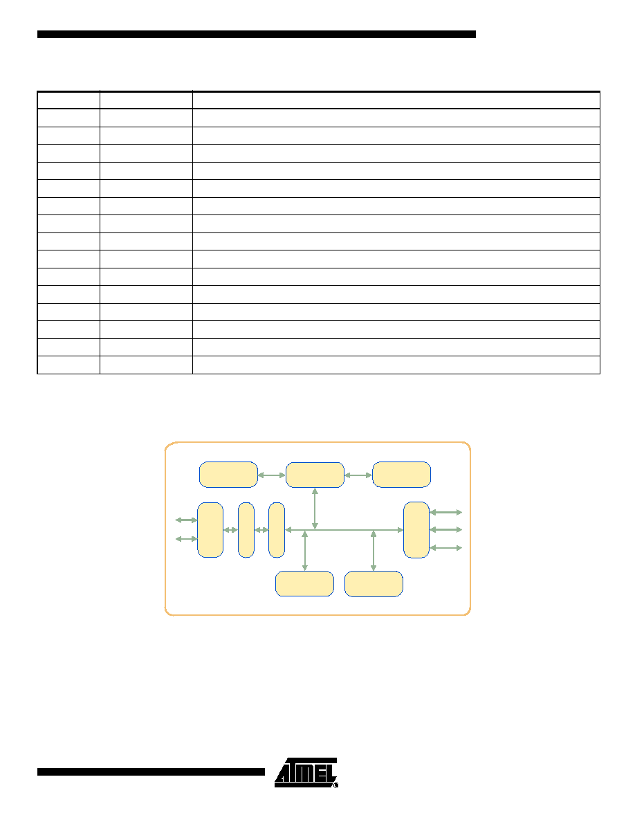
The on-chip USB hardware features a USB transceiver, a serial interface engine (SIE),
a SIE controller, and an SOF generation block. It supports the physical and data link
layer of the USB protocol whereas the USB transaction layer is implemented in
firmware.
In host mode, the integrated USB firmware consists of the Host USB Controller Driver
(HUSBCD) running on the USB Controller (USBC) and the Host System Interface
Controller Driver (HSICD) resident on the System Interface Controller (SIC). The
HUSBCD provides complete USB protocol management including device enumera-
tion, transaction managem ent, scheduling and frame management, and bus
reclamation. The HSICD serves as an interface between the HUSBCD and applica-
tions resident on the external system processor. It handles all of the high-level data
flow management during a USB transaction. Together, the HUSBCD and the HSICD
deliver complete USB host operations autonomously, without the intervention of the
system processor.
USB 2.0
Full-Speed
Host/Function
Processor
AT43USB370
Rev. 3340BUSB12/03

2
AT43USB370
3340BUSB12/03
The AT43USB370 communicates with the external system processor through its generic
32-bit host processor interface. This system interface contains 2 Kbytes of FIFO and a DMA
engine designed to ensure maximum bus utilization. The automatic USB retry mechanism
minimizes data traffic across the system interface.
As a function, the AT43USB370 operates in full-speed mode. It supports one control endpoint
and a maximum of six programmable (maximum packet size and endpoint type) endpoints.
The internal USB controller runs the function firmware that manages USB enumeration and
data flow control without system processor intervention.
Communication between the AT43USB370 firmware and applications resident in the system
processor is realized through a small set of ANSI C compliant, system interface Application
Protocol Interfaces (APIs). This API set encapsulates the complete USB functionality. It is
used as the basic building blocks for constructing application specific USB device drivers of
any type.
The AT43USB370, with its highly integrated USB hardware/firmware architecture, not only
hides the complexity of the traditional USB design, but also frees system resources from being
burdened by timing critical USB activities. It is an ideal solution for point-to-point USB connec-
tivity in the resource constrained embedded environment.
Pin
Configuration
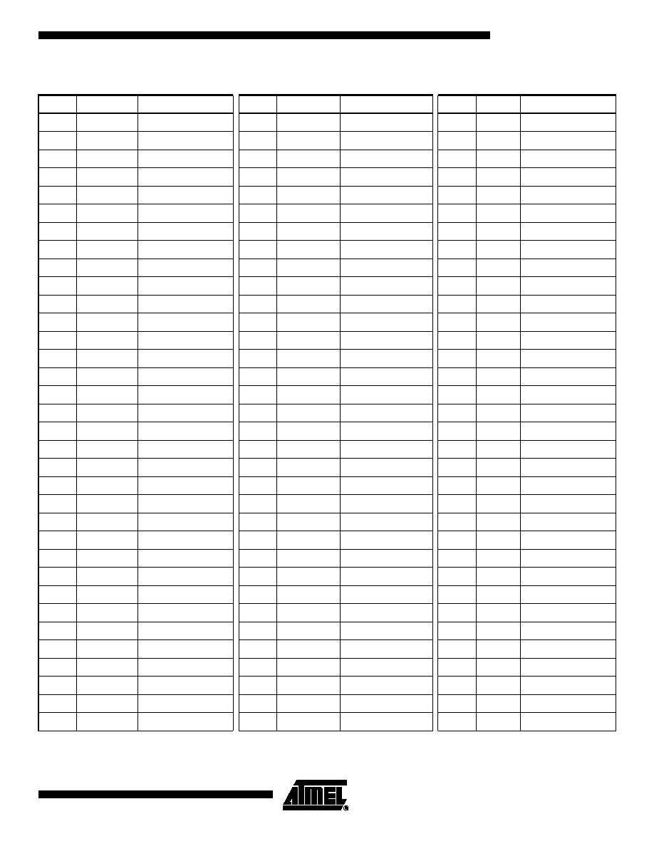
Figure 1. AT43USB370 100-lead LQFP
A7
A6
A5
A4
A3
A2
A1
A0
CS_N
OE_N
SELECT
INTR_IN
INTR_OUT
VDD
VSS
VSS
VDD18
PROG
MORE
READY
DONE
BUSY
WAIT_N
WE_N
DREQ_N
VSS
D20
D21
D22
D23
VDD
D24
D25
D26
D27
VSS
D28
D29
D30
D31
VDD18
VSS
NC
NC
SCAN_EN
RCV_DATA
DCLK
TRST_N
VSS
VDD
DACK_N
VSS
BT
MT
VDD
TP0
TP1
CLK_SEL
VSS
XTAL1
XTAL2
VDD18
LFT
VSS
DM
DP
TP2
TP3
RPD_EN
RPU_EN
RESET_N
TCK
TMS
TDI
TDO
D0
D1
D2
D3
D4
D5
D6
D7
VSS
D8
D9
D10
D11
VDD
D12
D13
D14
D15
NC
VDD18
VSS
D16
D17
D18
D19
1
2
3
4
5
6
7
8
9
10
11
12
13
14
15
16
17
18
19
20
21
22
23
24
25
75
74
73
72
71
70
69
68
67
66
65
64
63
62
61
60
59
58
57
56
55
54
53
52
51
100
99
98
97
96
95
94
93
92
91
90
89
88
87
86
85
84
83
82
81
80
79
78
77
76
26
27
28
29
30
31
32
33
34
35
36
37
38
39
40
41
42
43
44
45
46
47
48
49
50

4
AT43USB370
3340BUSB12/03
Pin Description
Pin Name
Type
Description
A[7:0]
Input
ADDRESS BUS System Address Bus
CS_N
Input
CHIP_SELECT from System Processor. Active Low
OE_N
Input
OUTPUT_ENABLE from System Processor. Active Low
SELECT
Input
PROCESSOR_SELECT from System Processor used to select between the USB Controller
(USBC) and System Interface Controller (SIC) when firmware is downloaded to these controllers
through the System Processor. Logic "1" selects SIC and Logic "0" selects USBC.
INTR_IN
Input
Interrupt to AT43USB370 from System Processor. Active High
INTR_OUT
Output
Interrupt from AT43USB370 to System Processor. Active High
VDD
Power Supply/Gnd
3.3V Power Supply
VSS
Power Supply/Gnd
Ground
VDD18
Power Supply/Gnd
1.8V Power Supply
PROG
Input
PROGRAM_LOAD_ENABLE from System Processor used when the program is
downloaded in the USB Controller and System Interface Controller through the System
Processor. Active High
MORE
Input
PIO Mode Handshake Signal from System Processor. Active High
READY
Output
READY to System Processor used when the program is downloaded in the USB Controller
and System Interface Controller through the System Processor. Active High
DONE
Input
DONE from System Processor used when the program is downloaded in the USB Controller
and System Interface Controller through the System Processor. Active High
BUSY
Output
BUSY to System Processor used when the System Interface Controller is busy in an
interrupt service routine and does not want the System Processor to issue an interrupt. Active
High
WAIT_N
Output
WAIT to System Processor. Active Low
WE_N
Input
WRITE_ENABLE from System Processor. Active Low
DREQ_N
Output
DMA Request to System Processor used to signal to the System Processor that the
AT43USB370 wants to start a DMA transfer. Active Low
DACK_N
Input
DMA Acknowledge from System Processor. Active Low
BT
Input
BIST Test Signal
MT
Input
Memory Test Signal
TP0
Input
Test Pin 0
TP1
Output
Test Pin 1
TP2
Input
Test Pin 2
TP3
Input
Test Pin 3
CLK_SEL
Input
External/PLL Clock Selection Low selects crystal-PLL clock source while a High uses
XTAL1, bypassing the PLL.
XTAL1
Input
Oscillator Input Input to the inverting oscillator amplifier.
XTAL2
Output
Oscillator Output Output of the inverting oscillator amplifier.
LFT
Input
PLL Loop Filter For proper operation of the PLL, this pin should be connected through a
2.2 nF capacitor in parallel with a 470
resistor in series with a 22 nF capacitor to ground
(VSS). Both capacitors must be high quality ceramic.