APEX MICROTECHNOLOGY CORPORATION · TELEPHONE (520) 690-8600 · FAX (520) 888-3329 · ORDERS (520) 690-8601 · EMAIL prodlit@apexmicrotech.com
1
PRELIMINARY
INTRODUCTION
The EK60 evaluation kit is designed to provide a convenient
way to breadboard design ideas for the PA78EU power opera-
tional amplifiers. The EVAL60 evaluation board is pre-wired for
all required and recommended external components including
the ones for power supply bypassing, compensation and cur-
rent limiting. The EVAL60 also includes a breadboard area for
constructing your application circuit with provisions for a pre-
amplifier to drive the PA78 inputs.
PARTS LIST
Apex Part #
Description
Quantity
HS27
Heatsink, Apex
1
EVAL60
PC Board, Apex
1
TW12
Thermal Washer, Apex
1 Box
OX7R105KWN 1 uF Cap 3530B105K501N
2
Novacap,
200V Breakdown
140-500N5-330J 33pF Cap CDR-500N5-330KS
1
XICON
146510CJ
BNC Connector
3
MS02
Socket Strip
1 bag
MS11
Socket Strip
1 bag
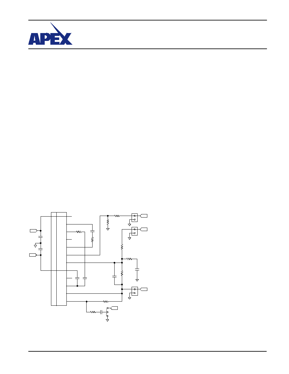
EK60 SCHEMATIC
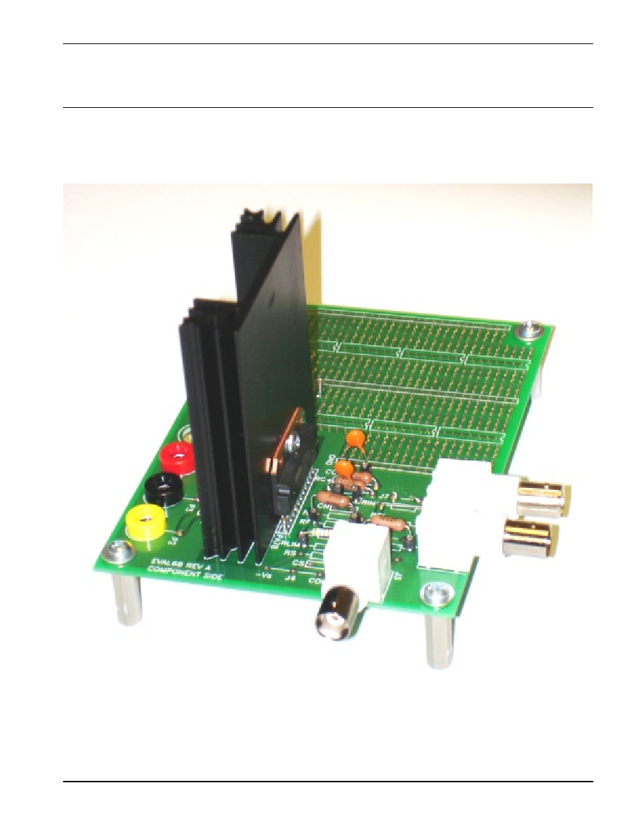
ASSEMBLY
During assembly refer to Figure 1 and Figure 2.
1. Solder surface mount ceramic capacitors C4 and C5 on the
DUT side of the board.
2. Add components for compensation (CC-, CC+, RC- and RC+)
based on the closed loop gain and capacitive load. Add the
current limit resistor (RLIM) based on load requirements (a
minimum value of 4.5 ohms should be used to protect the
PA78 internal output devices). It is recommended to use
MSO2 sockets for the components for quick component
changes on the board. Add 33pF capacitor (CT) between
DUT pins 3 and 5.
3. While developing your application circuit you will probably
want to use the mating socket strip. Use the MS11 socket
strip for mounting the PA78 EU. Clip off the strip after the
12th position. Insert the strip into the circuit board on the
DUT side and solder one pin on the reverse side. Check
whether the mating socket strip is fully seated against the
circuit board and then solder the remaining pins. Insert the
amplifier fully into the socket strip, noting the pin 1 location
on the amplifier and the circuit board.
4. For high power applications (see PA78EU datasheet for
SOA considerations) mount the heat sink (HS27) in the
outlined area on the circuit board.
5. If a heat sink is used, position the thermal washer behind
the amplifier in such a way that the hole on the washer
coincides with the hole on the tab and the heat sink.
6.
For high slew rate performance connect the heat tab to
a stable reference (see PA78U datasheet for details).
7. Install the banana jacks for P1 (+Vs), P2 (-Vs) and P3 (GND)
as shown in figure 1 and 2. There are provisions for two
extra banana jacks (P4 and P5) and can be used if desired
for external connections.
APEX MICROTECHNOLOGY CORPORATION · TELEPHONE (520) 690-8600 · FAX (520) 888-3329 · ORDERS (520) 690-8601 · EMAIL prodlit@apexmicrotech.com
3
PRELIMINARY
EVALUATION KIT
FOR PA78 PIN-OUT
EK60
This data sheet has been carefully checked and is believed to be reliable, however, no responsibility is assumed for possible inaccuracies or omissions. All specifications are subject to change without notice.
EK60U REV 3 JANUARY 2006 © 2006 Apex Microtechnology Corp.
Figure 2: Assembled PCB
