Sales Desk USA: Voice: (800) 544-2414 Fax: (315) 432-9121
Sales Desk Europe: Voice: (+44) 23 92 232392 Fax: (+44) 23 92 251369
Hybrid Couplers
3 dB, 90░
Caseless Components
4.1.33
Features
Ę Welded Tab Mount
Ę 2-Way Power Split
Ę Reliable Performance
Ę Handles 200 Watts
Applications
Ę Microstrip Circuits
Ę Divider/Combiners
Ę Switch Networks
Ę Balanced Detectors
Ę Antenna Feeds
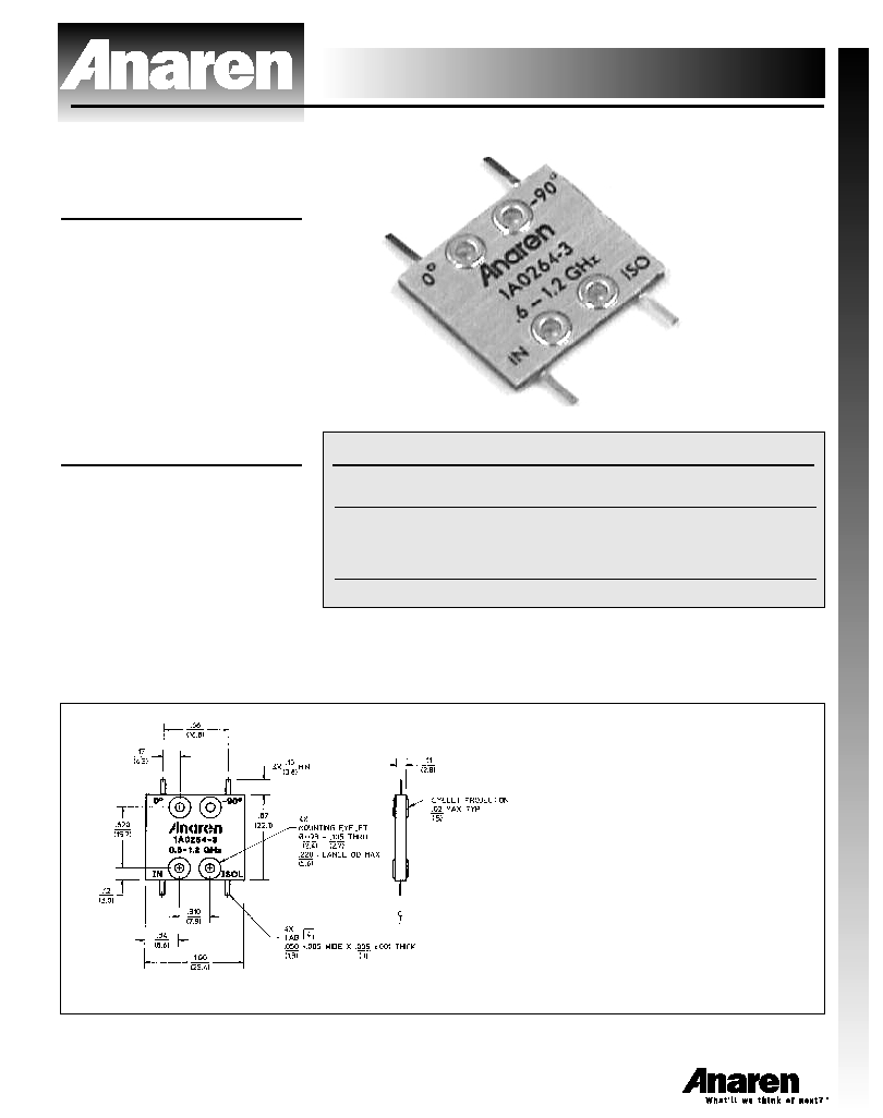
Outline Drawing
Electrical Specifications
Model 1A0264-3
Frequency
Isolation
Insert. Loss
VSWR
GHz
dB Min/Typ
dB Max
Max : 1
0.6 - 1.2
18/25
0.30
1.20/1.10
Amp. Bal.
Phase Bal.
Power
dB Max
Degrees Max
Ave. CW Watts
▒0.50
▒2.0
200
Notes: Electrical specifications apply only with properly designed test fixtures. Testing is done at ambient
temperature only. Sample testing is performed to MIL-STD-105, Level 2, AQL 1.0. Test includes coupling,
amplitude balance, insertion loss and isolation. If your application requires additional testing, consult Anaren
Power rating applies when solder tab/coupler interface has been conformally coated. Impedance: 50 ohms.
Meets MIL-E-5400 Class 3 requirements. Additional screening available for military and space applications.
Electrical and Mechanical Specifications subject to change without notice.
NOTES:
1. DIMENSIONS ARE IN INCHES OVER (MILLIMETERS)
2. MARKING SHALL BE IN ACCORDANCE WILL MIL-STD-130
3. FINISH: CHEMICAL CONVERSATION COAT (CLEAR)
PER MIL-C-5541, CLASS 1A
4. SOLDER TAB:
4.1 MATERIAL:FLAT WIRE, COPPER-061, PER ASTM-B-272
4.2 FINISH: GOLD PLATE PER MIL-G-45204, TYPE 3, GRADE A,
CLASS 00. OVER NICKEL SULFAMATE FLASH PER QQ-N-290,
CLASS I.