Alpha Industries, Inc. [781] 935-5150
∑ Fax [617] 824-4579 ∑ Email sales@alphaind.com ∑ www.alphaind.com
1
Specifications subject to change without notice. 11/99A
PHEMT GaAs IC High Linearity Positive
Control SPDT Switch DC≠2 GHz
Features
I High Linearity (50 dBm IP3 @ 0.9 GHz)
@ 3 V
I Low Insertion Loss (0.35 dB @ 0.9 GHz)
I +3 V Operation
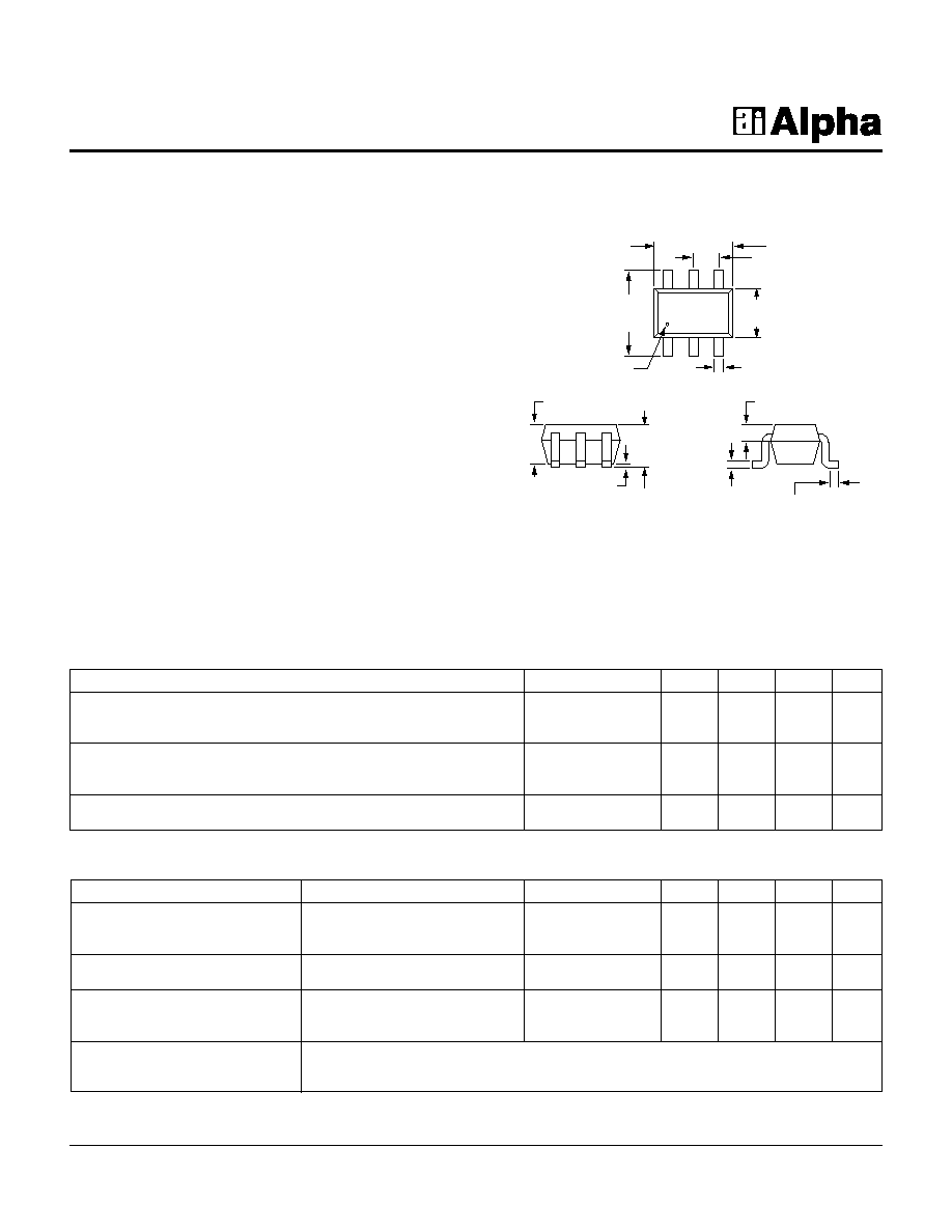
I Ultra Miniature SC-70 6 Lead Package
I PHEMT Process
SC-70 6 Lead
AS185-92
0.079 (2.00 mm)
Ī 0.008 (0.20 mm)
0.049 (1.25 mm)
Ī 0.004 (0.10 mm)
0.008 (0.20 mm)
Ī 0.004 (0.10 mm)
0.087 (2.20 mm)
Ī 0.008 (0.20 mm)
0.035 (0.90 mm)
Ī 0.004 (0.10 mm)
0.002 (0.005 mm)
Ī 0.002 (0.005 mm) 0.037 (0.95 mm)
Ī 0.006 (0.15 mm)
0.010 (0.25 mm)
Ī 0.006 (0.15 mm)
0.0055
(0.14 mm)
Ī 0.0015
(0.04 mm)
0.0256 (0.65 mm)
BSC
0.009 (0.23 mm)
REF
PIN 1 INDICATOR
Description
The AS185-92 is a PHEMT GaAs FET IC high linearity
SPDT switch in a SC-70 6 lead plastic package. This switch
has been designed for use where extremely high linearity,
low insertion loss and ultra miniature package size are
required. It can be controlled with positive, negative or a
combination of both voltages.
Some standard
implementations include antenna changeover, T/R and
diversity switching over 2 W. The AS185-92 switch can be
used in many analog and digital wireless communication
systems including cellular, GSM and DECT applications.
Parameter
1
Frequency
2
Min.
Typ.
Max.
Unit
Insertion Loss
3
DC≠0.5 GHz
0.45
0.6
dB
DC≠1.0 GHz
0.45
0.6
dB
DC≠2.0 GHz
0.55
0.7
dB
Isolation
DC≠0.5 GHz
25
28
dB
DC≠1.0 GHz
20
23
dB
DC≠2.0 GHz
14
17
dB
VSWR
4
DC≠1.0 GHz
1.2:1
1.4:1
DC≠2.0 GHz
1.3:1
1.8:1
Electrical Specifications at 25įC (0, +3 V)
Preliminary
Parameter
Condition
Frequency
Min.
Typ.
Max.
Unit
Switching Characteristics
5
Rise, Fall (10/90% or 90/10% RF)
60
ns
On, Off (50% CTL to 90/10% RF)
100
ns
Video Feedthru
50
mV
Input Power for 1 dB Compression
0/+3 V
0.9 GHz
+34
dBm
0/+5 V
0.9 GHz
+38
dBm
Intermodulation Intercept Point (IP3)
For Two-tone Input Power +17 dBm
0/+3 V
0.9 GHz
+50
dBm
0/+5 V
0.9 GHz
+57
dBm
Control Voltages
V
Low
= 0 to 0.2 V @ 20 ĶA Max.
V
High
= +3 V @ 100 ĶA Max. to +5 V @ 200 ĶA Max.
V
S
= V
High
Ī 0.2 V
Operating Characteristics at 25įC (0, +3 V)
1. All measurements made in a 50
system, unless otherwise specified.
2. DC = 300 kHz.
3. Insertion loss changes by 0.003 dB/įC.
4. Insertion loss state.
5. Video feedthru measured with 1 ns risetime pulse and 500 MHz bandwidth.

PHEMT GaAs IC High Linearity Positive Control SPDT Switch DC≠2 GHz
AS185-92
2
Alpha Industries, Inc. [781] 935-5150
∑ Fax [617] 824-4579 ∑ Email sales@alphaind.com ∑ www.alphaind.com
Specifications subject to change without notice. 11/99A
C
BL
C
BL
V
1
J
1
V
2
J
2
GND
J
3
C
BL
V
S
12
3
65
4
10 k
Pin Out
V
1
V
2
J
1
≠J
2
J
1
≠J
3
0
V
High
Isolation
Insertion Loss
V
High
0
Insertion Loss
Isolation
Truth Table
V
High
= +3 to +5 V (V
S
= V
High
Ī 0.2 V).
DC blocking capacitors (C
BL
) must be supplied externally.
C
BL
= 100 pF for operating frequency >500 MHz.
Typical Performance Data (0, +3 V)
Insertion Loss vs. Frequency
Frequency (GHz)
Insertion Loss (dB)
0.0
0.1
0.2
0.3
0.4
0.5
0.6
0.7
0.8
0.0
0.5
1.0
1.5
2.0
2.5
VSWR vs. Frequency
Frequency (GHz)
VSWR
1.0
1.1
1.2
1.3
1.4
1.5
1.6
1.7
1.8
1.9
2.0
0.0
0.5
1.0
1.5
2.0
2.5
Isolation vs. Frequency
Frequency (GHz)
Isolation (dB)
10
15
20
25
30
35
40
45
0.0
0.5
1.0
1.5
2.0
2.5
Characteristic
Value
RF Input Power
10 W Max. > 900 MHz
0/+7 V Control
Control Voltage
-0.2 V, +8 V
Operating Temperature
-40įC to +85įC
Storage Temperature
-65įC to +150įC
JC
25įC/W
Absolute Maximum Ratings