Alpha Industries, Inc. [781] 935-5150
· Fax [617] 824-4579 · Email sales@alphaind.com · www.alphaind.com
1
Specifications subject to change without notice. 2/00A
3343 GHz GaAs MMIC
Image Rejection Balanced Mixer
Features
I Low Conversion Loss, 9 dB
I Low LO Power Requirement, 8 dBm
I Image Rejection, 18 dB
I No DC Bias Required
I Requires External IF 90° Hybrid
Description
Alpha's image rejection balanced GaAs Schottky diode
mixer has a typical conversion loss of 9 dB at an LO power
level as low as 8 dBm over the band 3343 GHz. An
external 90° IF hybrid is required to combine the IF
1
and
IF
2
signals at the desired IF frequency. The chip uses
Alpha's proven Schottky diode technology, and is based
upon MBE layers for the highest uniformity and
repeatability. The diodes employ surface passivation to
ensure a rugged, reliable part with through-substrate via
holes and gold-based backside metallization to facilitate
an epoxy die attach process. All chips are screened for
DC diode parameters and lot samples are RF measured
to guarantee performance. This device is recommended
for applications requiring down conversion.
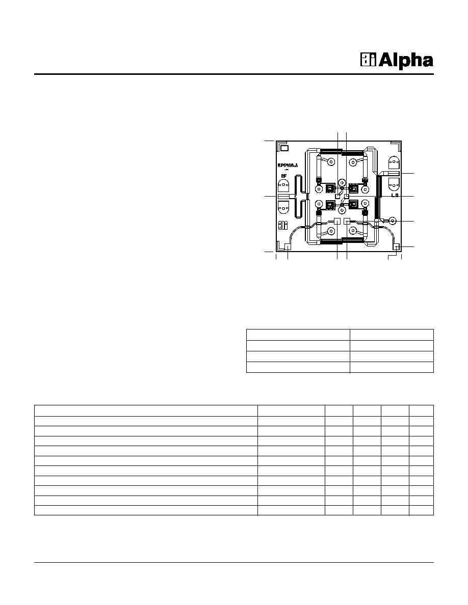
Dimensions indicated in mm.
All pads are
0.07 mm wide.
Chip thickness = 0.1 mm.
Chip Outline
Parameter
Symbol
Min.
Typ.
2
Max.
Unit
RF and LO Frequency Range
F
RF
, F
LO
3343
GHz
IF Frequency Range
F
IF
03
GHz
LO Power Level
P
LO
814
dBm
Conversion Loss
1
L
C
9
dB
Image Rejection
1
IR
18
dB
RF and LO Return Loss
1
RL
RF
, RL
LO
12
dB
LO to RF Isolation
1
ISO
LO-RF
12
dB
LO to IF Isolation
1
ISO
LO-IF
23
dB
RF Input 1 dB Compression Point
1
P
1 dB
7
dBm
Individual Diode Series Resistance
R
S
3.0
Electrical Specifications at 25°C
1
50 OHMS
50 OHMS
OHMIC ADDED 9-4-92
OHMIC ADDED 9-4-92
OHMIC ADDED 9-4-92
OHMIC ADDED 9-4-92
0.000
0.000
1.785
0.890
2.010
1.258
0.085
0.489
0.890
0.191
0.983
1.133
1.925
0.985
1.131
Absolute Maximum Ratings
Characteristic
Value
Operating Temperature
-55°C to +125°C
Storage Temperature
-65°C to +150°C
Total Input Power (RF + LO)
23 dBm
AM038R1-00
1. Not measured on a 100% basis.
2. Typical represents the median parameter value across the specified
frequency range for the median chip.

3343 GHz GaAs MMIC Image Rejection Balanced Mixer
AM038R1-00
2
Alpha Industries, Inc. [781] 935-5150
· Fax [617] 824-4579 · Email sales@alphaind.com · www.alphaind.com
Specifications subject to change without notice. 2/00A
Performance vs. LO Power
F
RF
= 40 GHz, F
LO
= 38 GHz, P
RF
= -10 dBm
LO Power (dBm)
Conversion Loss (dB)
Return Loss & Isolation (dB)
6
8
10
12
14
16
7
9
11
13
15
17
19
0
10
20
30
40
50
Conversion Loss
LO Return Loss
LO to RF Isolation
LO to IF Isolation
LO Power (dBm)
Image Rejection vs. LO Power
F
RF
= 40 GHz, F
LO
= 38 GHz, P
RF
= -10 dBm
Image Frequency = 36 GHz
0
5
10
15
20
25
7
9
11
13
15
17
19
Image Rejection (dB)
LO Frequency (GHz)
Image Rejection (dB)
0
5
10
15
20
25
31
32
33
34
35
36
37
38
Image Rejection vs. LO Frequency
F
RF
= F
LO
+ 2 GHz, P
LO
= 10 dBm
Image Frequency = F
LO
- 2 GHz
1
50 OHMS
50 OHMS
OHMIC ADDED 9-4-92
OHMIC ADDED 9-4-92
OHMIC ADDED 9-4-92
OHMIC ADDED 9-4-92
RF
LO
IF
1
IF
2
90° Phase Shifter/Splitter
0° Splitter
LO
IF
1
IF
2
RF
LO Frequency (GHz)
Conversion Loss (dB)
Return Loss & Isolation (dB)
6
8
10
12
14
16
31
32
33
34
35
36
37
38
0
10
20
30
40
50
Conversion Loss
LO Return Loss
LO to RF Isolation
LO to IF Isolation
Performance vs. LO Frequency
F
RF
= F
LO
+ 2 GHz, P
LO
= 10 dBm
Typical Performance Data
Wire Bonding Configuration
Circuit Schematic
IF ports bonded to IF hybrid.