Alpha Industries, Inc. [781] 935-5150
· Fax [617] 824-4579 · Email sales@alphaind.com · www.alphaind.com
1
Specifications subject to change without notice. 12/99A
Ka Band Power GaAs MESFET Chip
Features
I 21 dBm Output Power @ 18 GHz
I High Associated Gain, 9 dB @ 18 GHz
I High Power Added Efficiency, 25%
I Broadband Operation, DC40 GHz
I 0.25 µm Ti/Pd/Au Gates
I Passivated Surface
I Through-Substrate Via Hole Grounding
Description
The AFM04P2-000 is a high performance power GaAs
MESFET chip having a gate length of 0.25
µm and a
total gate periphery of 400
µm. The device has
excellent gain and power performance through 40 GHz,
making it suitable for a wide range of commercial and
military applications in oscillator and amplifier circuits. It
employs Ti/Pd/Au gate metallization and surface
passivation to ensure a rugged, reliable part. Through-
substrate via holes are incorporated into the chip to
facilitate low inductance grounding of the source for
improved high frequency and high gain performance.
AFM04P2-000
Parameter
Test Conditions
Min.
Typ.
Max.
Unit
Saturated Drain Current (I
DSS
)
V
DS
= 2 V, V
GS
= 0 V
90.0
140.0
190.0
mA
Transconductance (gm)
60.0
80.0
mS
Pinch-off Voltage (V
P
) V
DS
= 5 V, I
DS
= 1 mA
1.0
3.0
5.0
-V
Gate to Drain
I
GD
= -400
µA
8.0
12.0
-V
Breakdown Voltage (V
bgd
)
Output Power at 1 dB
21.0
dBm
Compression (P
1 dB
)
Gain at 1 dB Compression (G
1 dB
)
V
DS
= 5 V, I
DS
= 70 mA, F = 18 GHz
9.0
dB
Power Added Efficiency (
add) 25.0
%
Output Power at 1 dB
20.0
dBm
Compression (P
1 dB
)
Gain at 1 dB Compression (G
1 dB
)
V
DS
= 5 V, I
DS
= 70 mA, F = 30 GHz
5.0
dB
Power Added Efficiency (
add) 15.0
%
Thermal Resistance (
JC
) T
BASE
= 25°C
250.0
°C/W
Electrical Specifications at 25°C
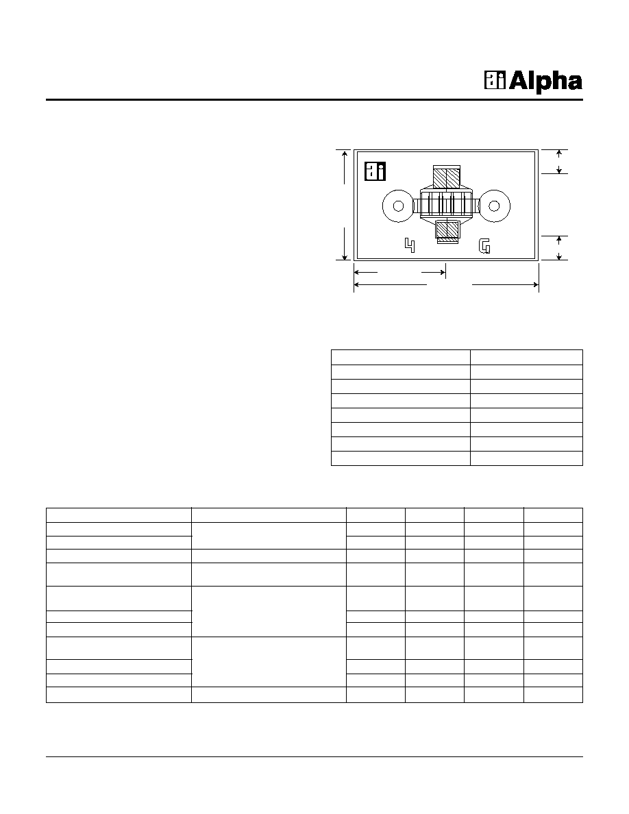
0.395 mm
0.327 mm
Drain
Gate
0.655 mm
0.110 mm
0.110 mm
Characteristic
Value
Drain to Source Voltage (V
DS
) 6
V
Gate to Source Voltage (V
GS
) -4
V
Drain Current (I
DS
) I
DSS
Gate Current (I
GS
) 1
mA
Total Power Dissipation (P
T
) 700
mW
Storage Temperature (T
ST
)
-65 to +150°C
Channel Temperature (T
CH
) 175°C
Absolute Maximum Ratings
Chip thickness = 0.1 mm.

2
Alpha Industries, Inc. [781] 935-5150
· Fax [617] 824-4579 · Email sales@alphaind.com · www.alphaind.com
Specifications subject to change without notice. 12/99A
Ka Band Power GaAs MESFET Chip
AFM04P2-000
Typical S-Parameters (V
DS
= 5 V, I
DS
= 70 mA)
Freq.
S
11
S
21
S
12
S
22
MAG
(GHz)
Mag.
Ang.
Mag.
Ang.
Mag.
Ang.
Mag.
Ang.
k
(dB)
2
0.969
-37.191
5.040
153.579
0.029
68.605
0.550
-18.296
0.100
22.364
3
0.958
-54.069
4.740
141.521
0.041
59.064
0.533
-26.529
0.150
20.613
4
0.935
-69.318
4.398
130.518
0.051
50.587
0.514
-33.959
0.200
19.278
5
0.913
-82.889
4.050
120.568
0.058
43.171
0.497
-40.630
0.250
18.247
6
0.893
-94.881
3.719
111.573
0.064
36.722
0.482
-46.663
0.299
17.658
7
0.877
-105.468
3.415
103.398
0.068
31.107
0.471
-52.183
0.349
17.104
8
0.863
-114.843
31.420
95.911
0.071
26.196
0.462
-57.310
0.398
16.464
9
0.852
-123.189
2.898
88.991
0.073
21.873
0.456
-62.138
0.447
15.986
10
0.843
-130.670
2.683
82.540
0.074
18.042
0.453
-66.738
0.496
15.566
11
0.836
-137.422
2.492
67.477
0.075
14.624
0.452
-71.161
0.544
15.193
12
0.831
-143.563
2.322
70.736
0.076
11.558
0.453
-75.442
0.593
14.858
13
0.826
-149.188
2.171
65.267
0.076
8.796
0.455
-79.606
0.641
14.447
14
0.823
-154.374
2.036
60.027
0.076
6.302
0.459
-83.671
0.688
14.285
15
0.821
-159.187
1.914
54.985
0.065
4.047
0.464
-87.648
0.735
14.037
16
0.819
-163.679
1.805
50.114
0.074
2.007
0.470
-91.546
0.781
13.811
17
0.818
-167.895
1.605
45.393
0.074
0.167
0.477
-95.372
0.827
13.063
18
0.817
171.872
1.615
40.805
0.073
-1.486
0.484
-99.129
0.872
13.412
19
0.817
-175.369
1.532
36.335
0.072
-2.961
0.492
-102.821
0.916
13.235
20
0.817
-179.221
1.456
31.973
0.071
-4.266
0.501
-106.451
0.959
13.071
21
0.818
177.359
1.386
27.760
0.060
-5.405
0.510
-110.021
1.001
12.753
22
0.819
174.083
1.321
23.535
0.069
-6.382
0.520
-113.533
1.041
11.534
23
0.820
170.936
1.261
19.445
0.068
-7.201
0.530
-116.989
1.069
10.915
24
0.821
167.905
1.205
15.343
0.067
-7.863
0.540
-120.389
1.116
10.431
25
0.822
164.969
1.512
11.498
0.066
-8.371
0.551
-123.737
1.150
10.024
26
0.824
162.148
1.103
6.633
0.065
-8.728
0.561
-127.031
1.181
9.671
27
0.825
159.403
1.057
3.836
0.064
-8.937
0.572
-130.275
1.210
9.358
28
0.826
156.737
1.013
0.105
0.063
-9.004
0.583
-133.468
1.235
9.080
29
0.829
154.144
0.972
-3.563
0.062
-8.937
0.594
-136.612
1.256
8.830
30
0.831
151.618
0.922
-7.169
0.062
-8.740
0.605
-139.606
1.273
8.604
31
0.833
149.155
0.895
-10.714
0.061
-8.427
0.616
-142.754
1.285
8.403
32
0.835
146.649
0.860
-14.200
0.061
-8.010
0.627
-145.754
1.292
8.222
33
0.836
144.398
0.826
-17.627
0.061
-7.502
0.638
-148.608
1.294
8.061
34
0.838
142.097
0.794
-20.996
0.061
-6.920
0.648
-151.615
1.291
7.920
35
0.840
139.845
0.764
-24.308
0.061
-6.281
0.659
-154.477
1.283
7.797
36
0.842
137.637
0.734
-27.563
0.061
-5.604
0.670
-157.293
1.270
7.694
37
0.844
135.472
0.706
-30.761
0.061
-4.907
0.680
-160.065
1.251
7.611
38
0.846
133.347
0.679
-33.903
0.061
-4.209
0.690
-162.693
1.228
6.550
39
0.848
131.261
0.653
-36.988
0.062
-3.525
0.700
-165.477
1.202
7.513
40
0.850
129.211
0.628
-40.017
0.063
-2.874
0.710
-168.117
1.171
7.504
S-Parameters include the effects of two 0.8 mil diameter bond wires, each 10 mil long, to each of the gate and drain terminals.

Parameter
Description
Unit
Default
BETA
Transconductance Coefficient
A/V
2
0.09464
V
PO
Pinch-off voltage
V
-1.8760
U
Mobility degradation fitting parameter
/V
0.3599
GAMA
Slope parameter of pinch-off voltage
0.03458
Q
Power law parameter
1.6560
NG
Subthreshold slope gate parameter
0.6025
ND
Subthreshold slope drain parameter
0.6050
DELT
Slope of drain characteristics in the saturated region
/A, V
0.5633
ALFA
Slope of drain characteristics in the linear region
/V
1.9400
T
Channel transmit-time delay
pS
6.4330
C
GSO
Gate-source Schottky barrier capacitance at V
GS
= 0
pF
0.4232
C
GDO
Gate-drain Schottky barrier capacitance at V
GS
= 0
pF
0.03138
V
BI
Built-in barrier potential
V
1.200
IS
Diode saturation current
A
0.563e-12
N
Diode ideality factor
1.1000
IBO
Breakdown saturation current
A
1.000e-16
NR
Breakdown ideality factor
10.0
V
BD
Breakdown voltage
V
20.00
RG
Gate terminal resistance
1.0000
RD
Drain terminal resistance
2.0000
RS
Source terminal resistance
0.8000
LG
Gate lead inductance
nH
0.5572
LD
Drain lead inductance
nH
0.2279
LS
Source lead inductance
nH
0.03532
CDS
Drain-source capacitance
pF
0.1555
RDSD
Channel trapping resistance
107.99
CDSD
Low frequency trapping resistance
nF
12.03
CGE
Gate-source electrode capacitance
fF
7.7240
CDE
Drain-source electrode capacitance
fF
9.4390
Ka Band Power GaAs MESFET Chip
AFM04P2-000
Alpha Industries, Inc. [781] 935-5150
· Fax [617] 824-4579 · Email sales@alphaind.com · www.alphaind.com
3
Specifications subject to change without notice. 12/99A
Power Derating
0
0.25
0.50
0.75
1.00
0
50
100
150
200
Total Power Dissipation P
T
(W)
T
BASE
(°C)
I-V
0
30
60
90
120
150
0
1
2
3
5
4
-0.5 V
-1.0 V
-1.5 V
-2.0 V
-2.5 V
V
DS
(V)
l
DS
(mA)
V
GS
= 0 V
Typical Performance Data
TOM-2 Model Parameters