Äîêóìåíòàöèÿ è îïèñàíèÿ www.docs.chipfind.ru
480
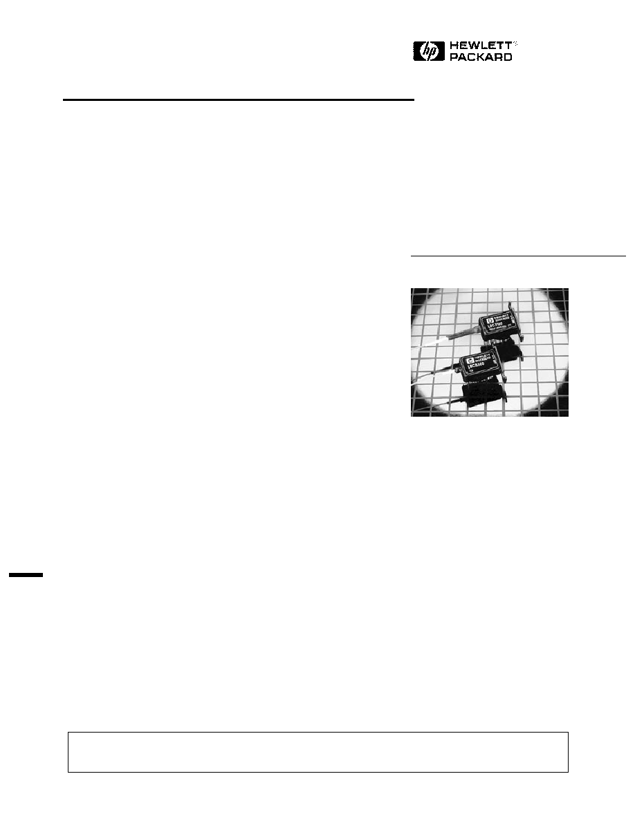
14 Pin DIL Uncooled Laser
Modules
Technical Data
LSC3X00
Features
· Low Cost Plastic Package
(14 Pin DIL)
· LSC3300: 100
µ
W (-10 dBm)
Min. Power Output
LSC3100: 1 mW (0 dBm)
Min. Power Output
· 1280 - 1330 nm Wavelength
· Hermetic Laser Module
· -40
°
C to +85
°
C Operation
Applications
· Telecommunications
· Local Area and Metropolitan
Area Networks
· Point to Point
Datacommunications
· Fiber Optic Sensors
· Cable Television
· Military Communications
and Control Systems
· Instrumentation
Description
LSC3X00 laser modules are high
reliability fiber optic light sources
operating in the 1300 nanometer
band. They are particularly well
suited for applications where low
power dissipation is required.
The internal semiconductor lasers
are based upon InGaAsP buried
heterostructure (BH) technology
and fabricated by the Metal-
Organic Vapor Phase Epitaxy
(MOVPE) process, resulting in
long lifetimes and modest
threshold currents.
The LSC3X00 package includes a
photodiode for monitoring the
laser output. A longhorn type
heatsink mounting flange is
incorporated in the industry
standard 14 pin DIL package.
Two basic varieties are offered
for alternative power ranges. The
"low power" LSC3300 covers the
power range between 100
µ
W
and 625
µ
W. The "high power"
LSC3100 uses the same laser
chip, but with tighter fiber
coupling to achieve output
powers from 1 mW to 2.5 mW.
The low cost outer package is
made feasible by our unique
design of hermetic miniature
laser submodule which houses
the electro-optic devices. The
submodule concept is used as a
building block in many other
Hewlett-Packard products
including cooled 1 mW 14 pin
lasers and DFB modules.
Laser Safety Warning
This device is a Class IIIb (3b) Laser Product. It may emit invisible laser radiation if operated with the fiber pigtail disconnected. To avoid
possible eye damage do not look into an unconnected fiber pigtail during laser operation. Do not exceed specified operating limits.
5963-1125E (7/94)
481
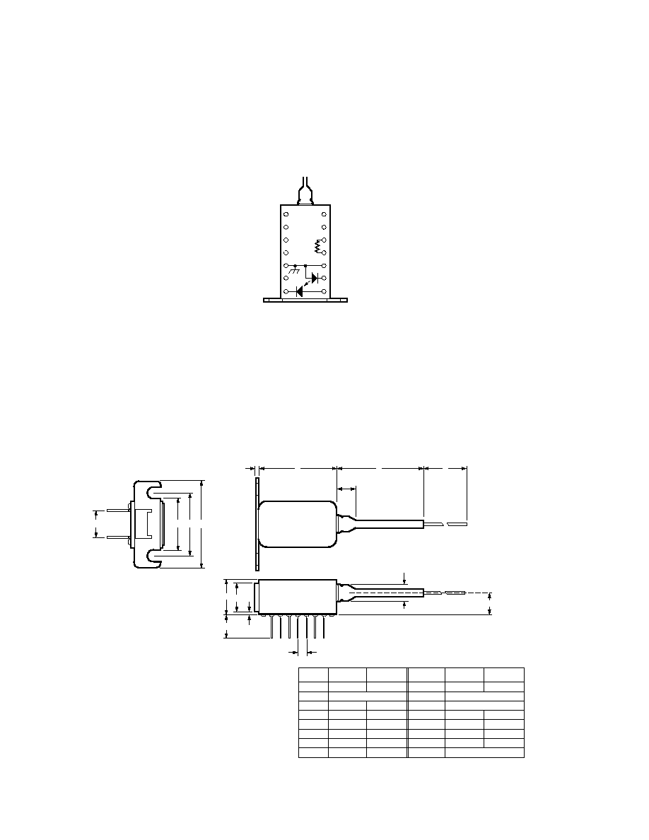
LSC3X00 Pin Connections and Block Diagram
Top View
LSC3X00 Mechanical Outline - Dimensions in mm
14 NOT CONNECTED
13 NOT CONNECTED
12 NOT CONNECTED
11 NOT CONNECTED
10 LASER ANODE (+), GROUND
9 LASER CATHODE (-)
8 MONITOR PHOTODIODE ANODE (-ve SUPPLY)
NOT CONNECTED 1
NOT CONNECTED 2
NOT CONNECTED 3
NOT CONNECTED 4
CASE GROUND 5
NOT CONNECTED 6
MONITOR PHOTODIODE CATHODE (+ve SUPPLY) 7
FIBER PIGTAIL
B C
A
R
Q
L
N
F
E
P
G
H
K
J
D
M
DIM.
MIN.
MAX.
A
B
C
D
E
F
G
H
12.6
19.05 NOM.
25.3
6.4
21.33
7.01
9.40
12.8
25.5
6.8
6.0
21.53
7.21
9.60
ALL DIMENSIONS IN MILLIMETERS
DIM.
MIN.
MAX.
J
K
L
M
N
P
Q
R
5.5
2.52 NOM.
25.0 NOM.
800
1.5
0.99
7.62 NOM.
5.9
4.2
1.8
1.05
482
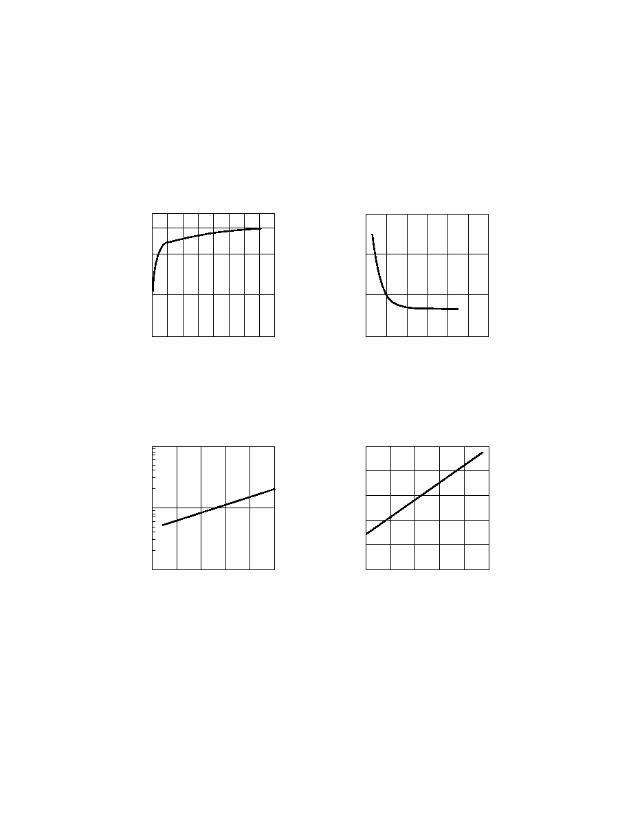
LSC3X00 Laser Diode Typical Operating Characteristics
dV/dl (
)
0
FORWARD CURRENT (mA)
20
50
30
30
20
10
40
0
60
DIFFERENTIAL RESISTANCE
vs. FORWARD CURRENT
10
NORMALIZED THRESHOLD CURRENT
-30
TEMPERATURE (°C)
50
30
10
-10
10
-1
70
THRESHOLD CURRENT
vs. TEMPERATURE
10
0
10
1
WAVELENGTH (nm)
-20
TEMPERATURE (°C)
60
40
20
0
80
PEAK WAVELENGTH
vs. TEMPERATURE
1300
1320
1310
1290
1285
FORWARD VOLTAGE (V)
0
FORWARD CURRENT (mA)
80
1.0
50
1.2
30
20
10
40
70
0.5
60
LASER FORWARD VOLTAGE
vs. FORWARD CURRENT
0
483
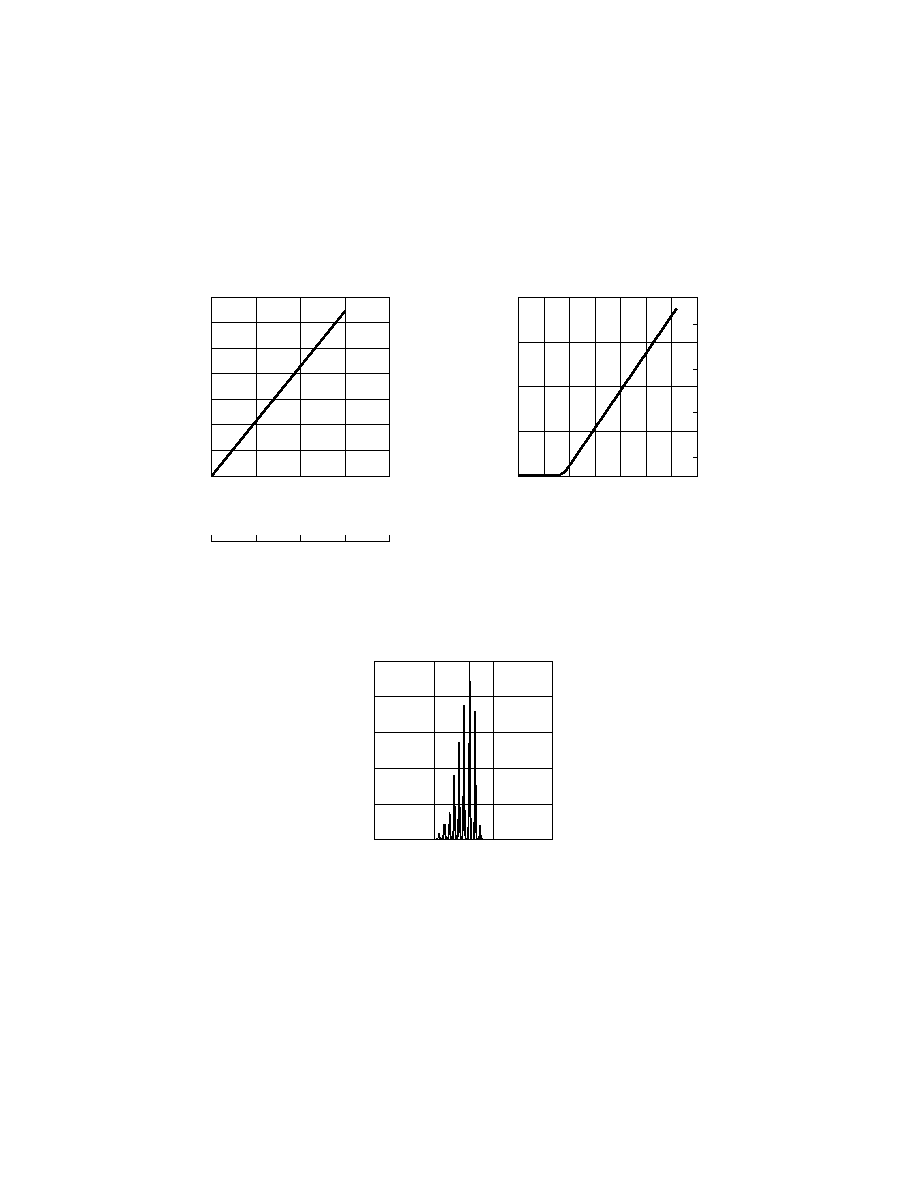
LSC3X00 Laser Diode Typical Operating Characteristics
0
FORWARD CURRENT (mA)
60
40
30
10
70
CONTINUOUS WAVE POWER
vs. FORWARD CURRENT (25 °C)
200
400
300
100
0
20
50
LSC3100 FIBER POWER (mW)
2 mW
1 mW
LSC3300 FIBER POWER (µW)
MONITOR DIODE PHOTOCURRENT (µA)
LSC3300 FIBER POWER (µW)
400
500
300
MONITOR PHOTOCURRENT
vs. OUTPUT POWER
600
100
100
200
300
700
400
200
2 mW
1 mW
LSC3100 FIBER POWER (mW)
0
RELATIVE POWER
1290
WAVELENGTH (nm)
1320
60
100
1300
40
1310
SPECTRAL CONTENT
80
20
0
484
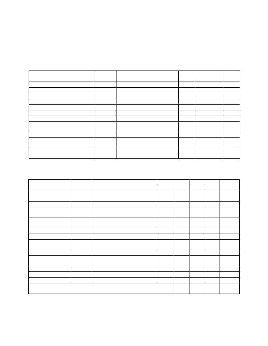
Absolute Maximum Ratings
Absolute maximum limits mean that no catastrophic damage will occur if the product is subjected to these ratings for short periods, provided
each limiting parameter is in isolation and all other parameters have values within the performance specification. It should not be assumed that
limiting values of more than one parameter can be applied to the product at the same time.
Limits
Parameter
Symbol
Conditions
Min.
Max.
Units
Laser Forward Current
If
DC
-
150
mA
Laser Reverse Current
Ir
DC
-
100
µ
A
Laser Reverse Voltage
Vlr
DC
-
2
V
Photodiode Reverse Voltage
Vr
DC
-
10
V
Photodiode Forward Current
Ipf
DC
-
1
mA
Operating Temperature
Tc
Pf min.
-40
+85
°
C
Storage Temperature
Ts
-40
+85
°
C
Relative Humidity
RH
0.0
non-
%RH
condensing
Fiber Pull Strength
-
10
N
Mechanical Shock
Mil Std 883D, Method 2002,
Condition B
Vibration
Mil Std 883D, Method 2007,
Condition A
Performance Specifications
LSC3300
LSC3100
Parameter
Symbol
Conditions
Min.
Max.
Min.
Max.
Units
LASER
CW, Tc = 25
°
C, Pf = Pf min.
unless otherwise stated
Threshold Current
Ith
5
35
5
35
mA
Peak Optical
Pf
100
-
1000
-
µ
W
Output Power
Optical Output
Pth
Pth = Pf @ Ith -2 mA
-
10
-
50
µ
W
Power
Slope Efficiency
4
16
40
100
µ
W/mA
Forward Voltage
Vf
-
1.8
-
1.8
V
Differential
Rd
dV/dI
-
10
-
10
Resistance
Centre Wavelength
c
Note 1
1280
1330
1280
1330
nm
Ic Change with
/
T
Tc = -40
°
C to 85
°
C
-
0.5
-
0.5
nm/
°
C
Temperature
Linewidth
FWHM (2.35s)
-
5
-
5
nm
Rise Time
r
10% to 90%: Ith to Pf = Pf min.
-
0.5
-
0.5
ns
Fall Time
f
90% to 10%: Pf = Pf min. to Ith
-
0.5
-
0.5
ns
Small Signal
Bw
Pf = Pf min.,
±
3 dB
1.0
-
1.0
-
GHz
Freq. Response
Note:
1. Modulated measurement available.
If the specific performance you require is not met by the above parameters, please contact Hewlett-Packard as the submodule
designs allows customization of performance to meet your needs.
Document Outline
- Features
- Applications
- Description
- LSC3X00 Pin Connections and Block Diagram
- LSC3X00 Mechanical Outline - Dimensions in mm
- LSC3X00 Laser Diode Typical Operating Characteristics
- LSC3X00 Laser Diode Typical Operating Characteristics
- Absolute Maximum Ratings
- Performance Specifications
- Fiber Pigtail: Tight jacketed, self-mode stripping, single mode fiber
- Ordering Information
- CDRH Certification
- Laser Warning