IrDA
®
Compliant 4 Mb/s 5 V
Infrared Transceiver
Technical Data
HSDL-3601#007
HSDL-3601#008
Features
·
Fully Compliant to IrDA 1.1
Physical Layer Specifications
- 9.6 kb/s to 4 Mb/s operation
·
Typical Link Distance
>
1.5 m
·
Compatible with ASK, HP-
SIR, and TV Remote
·
IEC825-Class 1 Eye Safe
·
Low Power Operation
- 4.75 V to 5.25 V
·
Small Module Size
- 4.0 x 12.2 x 5.1 mm
(HxWxD)
·
Complete Shutdown
- TXD, RXD, PIN diode
·
Low Shutdown Current
- 10 nA typical
·
Adjustable Optical Power
Management
- Adjustable LED drive-current
to maintain link integrity
·
Single Rx Data Output
- Speed select by FIR Select pin
·
Integrated EMI Shield
- Excellent noise immunity
·
Edge Detection Input
- Prevents the LED from long
turn-on time
·
Interface to Various Super
I/O and Controller Devices
·
Designed to Accommodate
Light Loss with Cosmetic
Window
·
Only 2 External Components
are Required
Applications
·
Digital Imaging
- Digital Still Cameras
- Photo-Imaging Printers
·
Data Communication
- Notebook Computers
- Desktop PCs
- Win CE Handheld Products
- Personal Digital Assistants
(PDAs)
- Printers
- Fax Machines, Photocopiers
- Screen Projectors
- Auto PCs
- Dongles
- Set-Top Box
·
Telecommunication
Products
- Cellular Phones
- Pagers
·
Small Industrial & Medical
Instrumentation
- General Data Collection
Devices
- Patient & Pharmaceutical
Data Collection Devices
·
IR LANs
Description
The HSDL-3601 is a low-profile
infrared transceiver module that
provides interface between logic
and IR signals for through-air,
serial, half-duplex IR data link.
The module is compliant to
IrDA Data Physical Layer
Specifications 1.1 and IEC825-
Class 1 Eye Safe.
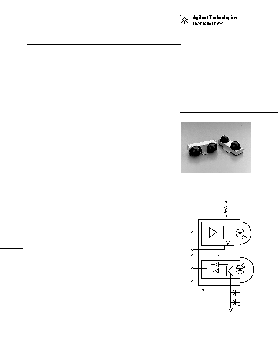
Functional Block Diagram
TXD (9)
MD0 (4)
MD1 (5)
RXD (8)
FIR_SEL (3)
GND (7)
AGND (2)
VCC (1)
R1
VCC
SP
HSDL-3601
CX1
CX2
LEDA (10)

2
Standard Package
Package Option
Package
Part Number
Increment
Front View
HSDL-3601#007
400
Front View
HSDL-3601#017
10
Top View
HSDL-3601#008
400
Top View
HSDL-3601#018
10
Application Support
Information
The Application Engineering
group in Agilent is available to
assist you with the technical
understanding associated with
HSDL-3601 infrared transceiver
module. You can contact them
through your local sales
representatives for additional
details.
The HSDL-3601 contains a high-
speed and high-efficiency 870 nm
LED, a silicon PIN diode, and
an integrated circuit. The IC
contains an LED driver and a
receiver providing a single
output (RXD) for all data rates
supported.
The HSDL-3601 can be
completely shut down to achieve
very low power consumption. In
the shut down mode, the PIN
diode will be inactive and thus
producing very little photo-
current even under very bright
ambient light. The HSDL3601
also incorporated the capability
for adjustable optical power. With
two programming pins; MODE 0
and MODE 1, the optical power
output can be adjusted lower when
the nominal desired link distance
is one-third or two-third of the full
IrDA link.
The HSDL-3601 comes in two
package options; the front view
option (HSDL-3601#007/#017),
and the top view option
(HSDL-3601#008/#018). All
options come with integrated
shield that helps to ensure low
EMI emission and high immunity
to EMI field, thus enhancing
reliable performance.
Ordering Information

3
I/O Pins Configuration Table
Pin
Description
Symbol
1
Supply Voltage
Vcc
2
Analog Ground
AGND
3
FIR Select
FIR_SEL
4
Mode 0
MD0
5
Mode 1
MD1
6
No Connection
NC
7
Ground
GND
8
Receiver Data Output
RXD
9
Transmitter Data Input
TXD
10
LED Anode
LEDA
Transceiver Control Truth Table
Mode 0
Mode 1
FIR_SEL
RX Function
TX Function
1
0
X
Shutdown
Shutdown
0
0
0
SIR
Full Distance Power
0
1
0
SIR
2/3 Distance Power
1
1
0
SIR
1/3 Distance Power
0
0
1
MIR/FIR
Full Distance Power
0
1
1
MIR/FIR
2/3 Distance Power
1
1
1
MIR/FIR
1/3 Distance Power
X = Don't Care
Transceiver I/O Truth Table
Transceiver
Inputs
Outputs
Mode
FIR_SEL
TXD
EI
LED
RXD
Active
X
1
X
On
Not Valid
Active
0
0
High
[1]
Off
Low
[3]
Active
1
0
High
[2]
Off
Low
[3]
Active
X
0
Low
Off
High
Shutdown
X
X
[4]
Low
Not Valid
Not Valid
X= Don't Care
EI = In-Band Infrared Intensity at detector
Notes :
1. In-Band EI
115.2 kb/s and FIR_SEL = 0.
2. In-Band EI
0.576 Mb/s and FIR_SEL = 1.
3. Logic Low is a pulsed response. The condition is maintained for duration dependent on the pattern and strength of the incident
intensity.
4. To maintain low shutdown current, TXD needs to be driven high or low and not left floating.
Functional Block Diagram
TXD (9)
MD0 (4)
MD1 (5)
RXD (8)
FIR_SEL (3)
GND (7)
AGND (2)
VCC (1)
R1
VCC
SP
HSDL-3601
CX1
CX2
LEDA (10)
8
7
6
5
4
3
2
1
9
10
8
7
6
5
4
3
2
1
9
10
BACK VIEW (HSDL-3601 #007/#017)
BOTTOM VIEW (HSDL-3601 #008/#018)
4
Recommended Application Circuit Components
Component
Recommended Value
R1
6.2
±
5%, 0.5 Watt, for 4.75
Vcc
5.25 V operation
CX1
[5]
0.47
µ
F
±
20%, X7R Ceramic
CX2
[6]
6.8
µ
F
±
20%, Tantalum
Notes:
5. CX1 must be placed within 0.7 cm of the HSDL-3601 to obtain optimum noise immunity.
6. In environments with noisy power supplies, supply rejection performance can be enhanced by
including CX2, as shown in "HSDL-3601 Functional Block Diagram" in page 3.
CAUTIONS: The BiCMOS inherent to the design of this component increases the component's
susceptibility to damage from electrostatic discharge (ESD). It is advised that normal static precautions
be taken in handling and assembly of this component to prevent damage and/or degradation which may
be induced by ESD.
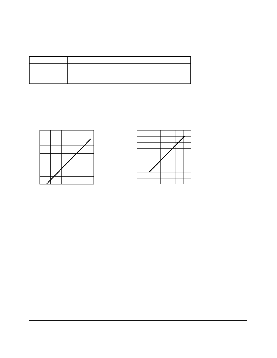
ILED (A)
0.7
LEDA VOLTAGE (V)
0.3
1.7
2.1
0
0.1
1.3
2.3
0.5
1.5
1.9
0.6
0.4
0.2
LOP (mW/sr)
450
ILED (A)
200
0.3
0.6
0
50
0
0.7
350
0.1
0.4
400
300
100
250
150
0.2
0.5
ILED vs. LEDA.
Light Output Power (LOP) vs. ILED.
Marking Information
The HSDL-3601#007/017 is marked
"3601YYWW' on the shield where "YY"
indicates the unit's manufacturing year,
and "WW" refers to the work week in
which the unit is tested.
The HSDL-3601#008/018 is marked a
"black" dot on the shield.
Ma

5
Absolute Maximum Ratings
[7]
Parameter
Symbol
Minimum
Maximum
Unit
Conditions
Storage Temperature
T
S
-40
+100
°
C
Operating Temperature
T
A
-20
+70
°
C
DC LED Current
I
LED
(DC)
165
mA
Peak LED Current
I
LED
(PK)
650
mA
90
µ
s pulse width,
25% duty cycle
750
mA
2
µ
s pulse width,
10% duty cycle
LED Anode Voltage
V
LEDA
-0.5
7
V
Supply Voltage
Vcc
0
7
V
Transmitter Data
I
TXD
(DC)
-12
12
mA
Input Current
Receiver Data
V
O
-0.5
Vcc+0.5
V
|I
O
(RXD)| = 20
µ
A
Output Voltage
Note:
7. For implementations where case to ambient thermal resistance
50
°
C/W.
Recommended Operating Conditions
Parameter
Symbol
Min.
Max.
Unit
Conditions
Operating Temperature
T
A
-20
+70
°
C
Supply Voltage
Vcc
4.75
5.25
V
Logic High Input Voltage
V
IH
2 Vcc/3
Vcc
V
for TXD, MD0, MD1,
and FIR_SEL
Logic Low Transmitter
V
IL
0
Vcc/3
V
Input Voltage
LED (Logic High) Current
I
LEDA
400
650
mA
Pulse Amplitude
Receiver Signal Rate
0.0024
4
Mb/s
Ambient Light
See IrDA Serial Infrared
Physical Layer Link
Specification, Appendix A
for ambient levels