APTDF200H170
A
P
T
D
F
200
H
170 R
e
v 0 M
a
y, 2005
APT website http://www.advancedpower.com
1 - 3
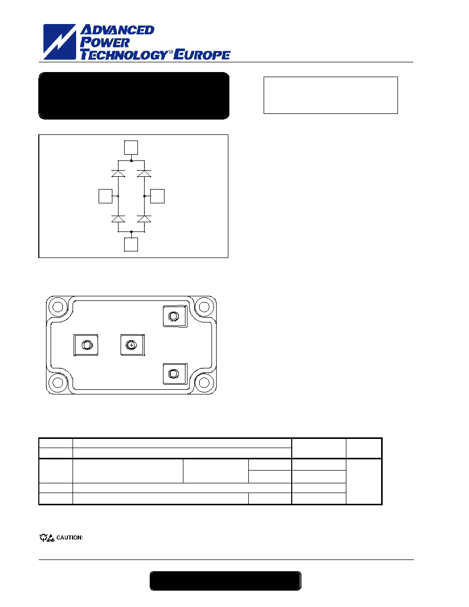
+
AC2
-
AC1
Absolute maximum ratings
Symbol Parameter
Max
ratings
Unit
V
R
Maximum DC reverse Voltage
V
RRM
Maximum Peak Repetitive Reverse Voltage
1700 V
T
c
= 25°C
240
I
F(A V)
Maximum Average Forward
Current
Duty cycle = 50%
T
c
= 55°C
200
I
F(RMS)
RMS Forward Current
250
I
FSM
Non-Repetitive Forward Surge Current
T
j
= 25°C
600
A
These Devices are sensitive to Electrostatic Discharge. Proper Handing Procedures Should Be Followed.
AC1
+
AC2
-
V
RRM
= 1700V
I
C
= 200A @ Tc = 55°C
Application
· Uninterruptible Power Supply (UPS)
· Induction heating
· Welding equipment
· High speed rectifiers
Features
· Ultra fast recovery times
· Soft recovery characteristics
· Very low stray inductance
· High blocking voltage
· High current
· Low leakage current
· Very low stray inductance
-
Symmetrical design
-
M5 power connectors
· High level of integration
Benefits
· Outstanding performance at high frequency
operation
· Low losses
· Low noise switching
· Direct mounting to heatsink (isolated package)
· Low junction to case thermal resistance
Fast Diode Rectifier Bridge
Power Module

APTDF200H170
A
P
T
D
F
200
H
170 R
e
v 0 M
a
y, 2005
APT website http://www.advancedpower.com
2 - 3
All ratings @ T
j
= 25°C unless otherwise specified
Electrical Characteristics
Symbol Characteristic
Test
Conditions
Min Typ Max Unit
T
j
= 25°C
2.2
2.5
V
F
Diode Forward Voltage
I
F
= 200A
T
j
= 125°C
2.1
V
T
j
= 25°C
350
I
RM
Maximum Reverse Leakage Current
V
R
= 1700V
T
j
= 125°C
600
µA
Dynamic Characteristics
Symbol Characteristic
Test
Conditions
Min Typ Max Unit
T
j
= 25°C
572
t
rr
Reverse Recovery Time
T
j
= 125°C
704
ns
T
j
= 25°C
40
Q
rr
Reverse Recovery Charge
T
j
= 125°C
70
µC
T
j
= 25°C
140
I
RRM
Reverse Recovery Current
I
F
= 200A
V
R
= 900V
di/dt = 2000A/µs
T
j
= 125°C
200
A
Thermal and package characteristics
Symbol Characteristic
Min Typ Max Unit
R
thJC
Junction
to
Case
0.18 °C/W
V
ISOL
RMS Isolation Voltage, any terminal to case t =1 min, I isol<1mA, 50/60Hz
3400 V
T
J
Operating junction temperature range
-40
150
T
STG
Storage Temperature Range
-40
125
T
C
Operating Case Temperature
-40
100
°C
To heatsink
M6
3
5
Torque Mounting
torque
For terminals
M5
2
3.5
N.m
Wt Package
Weight
280
g
Package outline
(dimensions in mm)
APTDF200H170
A
P
T
D
F
200
H
170 R
e
v 0 M
a
y, 2005
APT website http://www.advancedpower.com
3 - 3
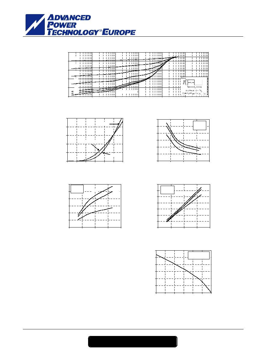
Typical Performance Curve
0.9
0.7
0.5
0.3
0.1
0.05
Single Pulse
0
0.04
0.08
0.12
0.16
0.2
0.00001
0.0001
0.001
0.01
0.1
1
10
Rectangular Pulse Duration (Seconds)
The
r
m
a
l
I
m
pe
da
nc
e
(
°
C
/
W
)
Maximum Effective Transient Thermal Impedance, Junction to Case vs Pulse Duration
T
J
=25°C
T
J
=25°C
T
J
=125°C
0
100
200
300
400
500
0.0
0.5
1.0
1.5
2.0
2.5
3.0
V
F
, Anode to Cathode Voltage (V)
I
F
,
F
o
r
w
a
rd
C
u
rre
n
t
(
A
)
Forward Current vs Forward Voltage
Trr vs. Current Rate of Charge
100 A
200 A
400 A
200
300
400
500
600
700
800
0
3000
6000
9000
12000
-di
F
/dt (A/µs)
t
rr
,
R
e
v
e
r
se R
e
co
ver
y T
i
m
e
(
n
s)
T
J
=125°C
V
R
=900V
QRR vs. Current Rate Charge
100 A
200 A
400 A
40
60
80
100
120
140
160
0
3000
6000
9000
12000
-di
F
/dt (A/µs)
Q
RR
,
R
e
v
e
r
se R
e
co
ver
y C
h
ar
g
e
(
µ
C
)
T
J
=125°C
V
R
=900V
IRRM vs. Current Rate of Charge
100 A
200 A
400 A
100
200
300
400
500
600
700
800
0
3000
6000
9000
12000
-di
F
/dt (A/µs)
I
RRM
,
R
eve
r
se R
e
c
o
ver
y C
u
r
r
en
t
(
A
)
T
J
=125°C
V
R
=900V
0
50
100
150
200
250
300
0
25
50
75
100
125
150
Case Temperature (şC)
I
F
(A
V
)
(
A
)
Max. Average Forward Current vs. Case Temp.
Duty Cycle = 0.5
T
J
=150°C
APT reserves the right to change, without notice, the specifications and information contained herein
APT's products are covered by one or more of U.S patents 4,895,810 5,045,903 5,089,434 5,182,234 5,019,522
5,262,336 6,503,786 5,256,583 4,748,103 5,283,202 5,231,474 5,434,095 5,528,058 and foreign patents. U.S and Foreign patents pending. All Rights Reserved.