
EVAL - ADM1023
a
REV. A 11/10/99
Information furnished by Analog Devices is believed to be accurate and
reliable. However, no responsibility is assumed by Analog Devices for its
use, nor for any infringements of patents or other rights of third parties
which may result from its use. No license is granted by implication or
otherwise under any patent or patent rights of Analog Devices.
One Technology Way, P.O. Box 9106, Norwood, MA 02062-9106, U.S.A.
Tel: 781/329-4700
World Wide Web Site: http://www.analog.com
Fax: 781/326-8703
Analog Devices, Inc., 1998
Evaluation Board for Microprocessor
System Temperature Monitor
Preliminary Technical Data
PRELIMINAR
Y
TECHNICAL
DA
TA
FEATURES
Next Generation upgrade to the ADM1021
On-Chip and Remote Temperature Sensing
Offset Registers for System Calibration
1°C Accuracy and Resolution on Local Channel
0.125°C Resolution/1°C Accuracy on Remote Channel
Programmable Over/Under Temperature Limits
Programmable Conversion Rate
2-Wire SMBus Serial Interface
Supports System Management Bus (SMBus
TM
TM
TM
TM
TM
) Alert
160
µµ
µµ
µ
A Max Operating Current
3
µ
µ
µ
µ
µ
Standby Current
3V to 5.5V Supply
Small 16-Lead QSOP Package
APPLICATIONS
Desktop Computers
Notebook Computers
Smart Batteries
Industrial Controllers
Telecoms Equipment
Instrumentation
I N T R O D U C T I O N
The ADM1023 Evaluation Board allows the ADM1023
microprocessor system temperature IC to be quickly and
easily evaluated using a personal computer. Using the
evaluation board and its accompanying software the
ADM1023 can be interfaced to any personal computer
running Windows
TM
95 or Windows
TM
98, via the
computer's parallel printer port.
The evaluation board allows the input and output
functions of the ADM1023 to be exercised without the
need for external components. The software allows control
and monitoring of the ADM1023's internal registers.
THE ADM1023
The following is a brief description of the ADM1023 and
a system overview. Further information can be found in
the datasheet for the device.
The ADM1023 is a hardware temperature monitor for
personal computers and other microprocessor systems
which features a two-channel digital thermometer and
over/under temperature alarm.
The device can measure the temperature of a
microprocessor using on-chip diode connected transistor
or can use a low cost small signal transistor such as the
2N3904 or the 2N3906. The measurment technique
cancels the absolute value of the transistor's base emitter
voltage, so that no calibration is required.
EVALUATION SYSTEM PACKAGE CONTENTS
The evaluation system contains the following items
This application note
ADM1023 Evaluation Board
Centronics Cable
Evaluation Software on 3 floppy disks
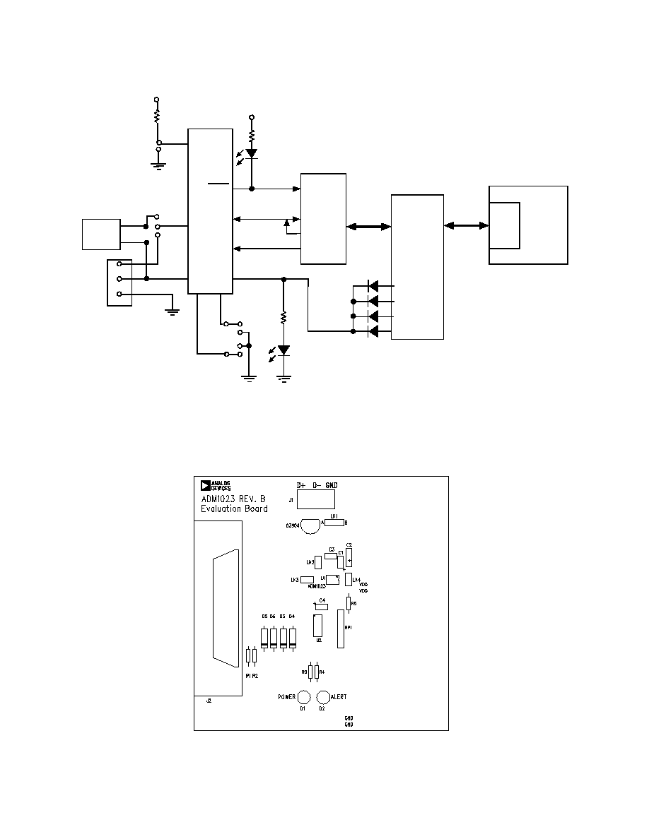
EVALUATION BOARD HARDWARE
The ADM1023 evaluation board contains the following
main components which can be identified from the block
diagram, printed circuit board silk screen and schematic
diagram of figures 1, 2 and 3 overleaf.
ADM1023 IC
NPN sensor transistor
LED indicators for power and Alert
Jumpers for selecting sensor and for setting SMBus
address
Interface buffers
Connector for parallel interface
Test connector for connecting to CPU Transistor
TM
Windows is a registered trademark of Microsoft Corporation
EVAL-ADM1023
2
REV. A
Preliminary Technical Data
PRELIMINAR
Y
TECHNICAL
DA
TA
Figure 1. ADM1023 Evaluation Board Block Diagram
Figure 2. ADM1023 Evaluation Board SilkScreen
N P N
S E N S O R
A D M 1 0 2 3
P C
BU F F E R S
36 -W AY
CE N T R O NI C S
C O N N E C T O R
(J 2 )*
PA
RA
LL
EL
PO
R
T
AL E R T
S D AT A
S C L K
E X T E R NA L
S E N S O R
T E S T
C O N N E C T O R
J 1
D 1
G R E E N
P O W E R
V
D D
V
D D
D +
D -
L K1
A D D 1
A D D 0
S T B Y
L K4
V
D D
D 2
R E D
AL E R T
D+
D-
G ND
4K7
R5
L K3
L K2
B
A
EVAL-ADM1023
3
REV. A
Preliminary Technical Data
PRELIMINAR
Y
TECHNICAL
DA
TA
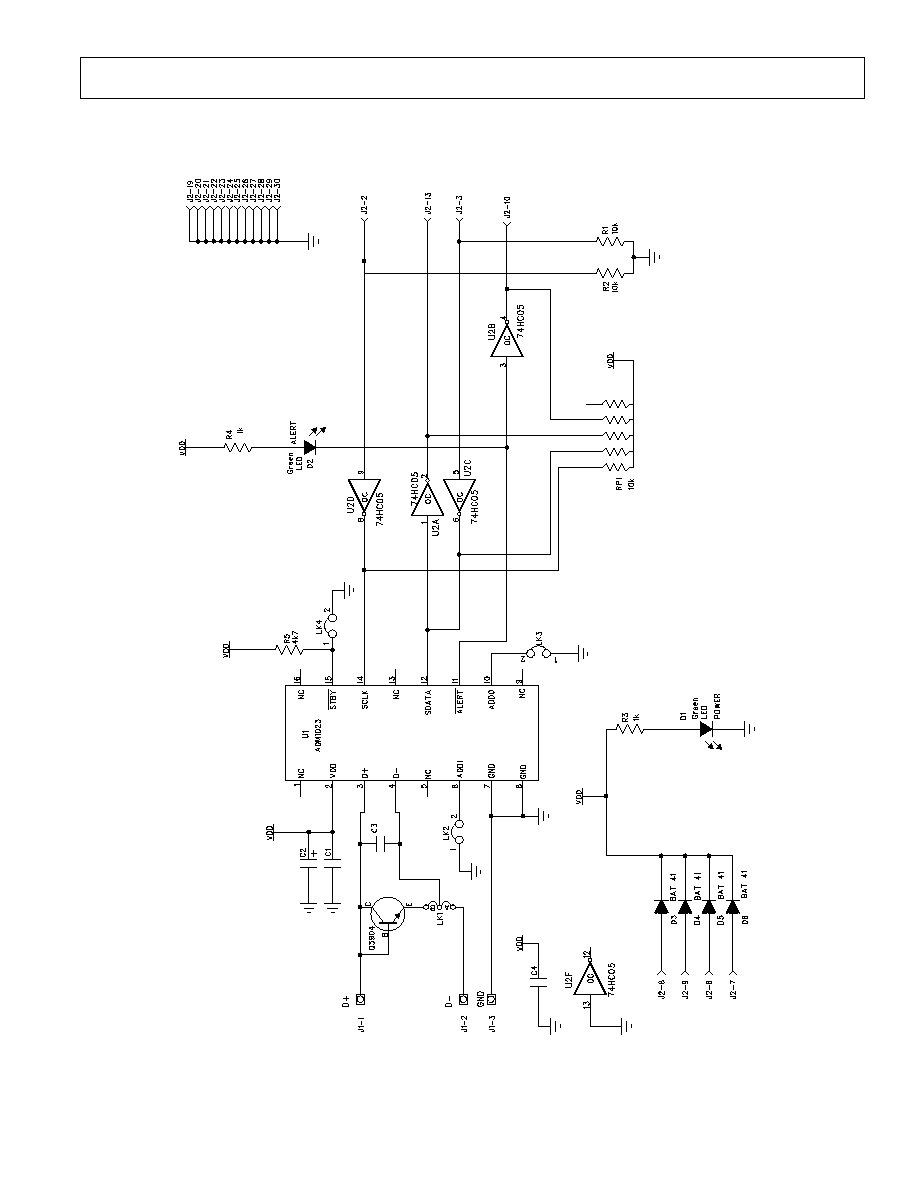
Figure 3. ADM1023 Evaluation Board Schematic

EVAL-ADM1023
4
REV. A
Preliminary Technical Data
PRELIMINAR
Y
TECHNICAL
DA
TA
CONNECTORS, SWITCHES AND INDICATORS
The function of the various connectors, links and
indicators on the evaluation board are explained below.
TEST CONNECTOR
Test Connector J1 allows an external diode to be
connected between the D+ and D- terminals of the
ADM1023
CENTRONICS INTERFACE CABLE
The evaluation board and the personal computer may be
connected via the printer parallel port using the contronics
cable provided. The connections to J2 are as follows.
REMOTE SENSOR SELECT LK1
The function of this jumper is to allow the user to choose
between measuring tempertature using the on-board
remote sensor and an external one connected between the
D+ and D- terminals of J1. When the middle pin is linked
to B the on-board sensor is used and when the middle pin
is linked to A the off-board sensor is used.
STANDBY INPUT LK4
The ADM1023 has an active low standby input, pin 15
controlled by LK4 on the evaluation board. This is a logic
input that enables selection between normal operation
(high) and standby operation (low). Without the shorting
link the pin is high (normal mode). With the shorting link
the pin is low (standby mode). This input performs the
same function as bit 7 of the status register
TABLE 1. ADM1023 SENSOR SELECTION
LK1 Position Sensor Selected
A
External Sensor
B
On-baord NPN Sensor
SERIAL BUS ADDRESS SELECT
LK2 and LK3 are used to set the two LSB's of the
ADM1023's serial bus address, ADD0 and ADD1. These
pins are tri-state and can be grounded, left unconnected or
tied to V
DD
. This means a total of nine addresses are
possible. However for simplicity on the evaluation board a
jumper is used to allow each pin two states ( 4 Addresses).
The pin is floating when the shorting link is not on the
board. The pin is grounded when the shorting link is
placed on the board. It should be noted that ADD0 and
ADD1 are only read at power up. If LK2 or LK3 are
changed while the ADM1023 is on, the change of address
will not be effective until the device has been powered off
and then on again.
As the serial bus address is seven bits, when storing it as
an 8-bit word it must be left or right justified, with either
the MSB or the LSB of the 8-bit word as zero. The
ADM1023 evaluation software stores the 7-bit serial bus
address as left justified and makes the LSB zero. Table 2
shows the four possible addresses possible on the
evaluation board
TABLE 2. ADM1023 DEVICE ADDRESSES
Address Pins
Device Address
ADD1 (LK2) ADD0 (LK3) Binary Hex
0(LK2 Closed) 0(LK3 Closed) 0011000(0) 0
0(LK Closed)
NC(LK Open) 0011001(0) 32
NC(LK2 Open) 0(LK3 Closed) 0101001(0) 52
NC(LK2 Open) NC(LK3 Open) 0101010(0) 54

EVAL-ADM1023
5
REV. A
Preliminary Technical Data
PRELIMINAR
Y
TECHNICAL
DA
TA
Fig 4. Evaluation Software Startup Screen
THE SOFTWARE
The software allows the ADM1023's functions to be
controlled from the PC via an easy to use interface
operating under the Windows
TM
environment. The
contents of the devices internal registers can easily be read
or altered through a user-friendly graphics interface, while
the Control Centre window allows the graphing of the
temperature readings.
INSTALLING THE SOFTWARE
To install the software, insert the first disk of the program
software into drive A, click on the Start icon, click on
Run, then type A:setup.exe as the file name. If the 3.5inch
floppy disk drive is not drive "A" then type "X" instead of
"A" where "X" is the drive letter of the 3.5-inch floppy
disk drive.
USING THE SOFTWARE
When using the software, first ensure the evaluation board
is connected to the Parallel Printer Port.
To start the software, select Start-Programs-Analog
Devices-ADM1023 Eval Software.
When the program is started, a startup screen will appear.
Press any key or mouse button to go onto the next step,
which is the Software Initialisation Wizard.